VVNB — HA NOI/NOI BAI INTL
VVNB AD 2.1 AERODROME LOCATION INDICATOR AND NAME
VVNB — HA NOI/NOI BAI INTL
VVNB AD 2.2 AERODROME GEOGRAPHICAL AND ADMINISTRATIVE DATA
| 1 |
ARP coordinates and site at AD |
211318N - 1054820E Intersection of RWY 11L/29R and TWY N3 |
| 2 |
Direction and distance from (city) | 28 KM North from Ha Noi city |
| 3 |
Elevation/Reference temperature | 13 M/34°C |
| 4 |
Geoid undulation at AD ELEV PSN | NIL |
| 5 |
MAG VAR/Annual change | 2° W (2022)/NIL |
| 6 |
Name of aerodrome operator, address, telephone,telefax numbers, e-mail address, AFS address and, ifavailable, website address |
Post: Post: Civil Aviation Authority of Viet Nam (CAAV) Telephone: +84 24 38840114 ext: 625 Fax: +84 24 38542396 Email: naa@naa.gov.vn AFS: VVNBYAYX URL: NIL |
|
Post: Post: Airports Corporation of Viet Nam (ACV) Telephone: +84 24 38865047 Fax: +84 24 38865540 Email: vanthu.han@acv.vn AFS: VVNBYDYX URL: NIL | ||
| 7 |
Types of traffic permitted (IFR/VFR) | IFR/VFR |
| 8 |
Remarks | NIL |
VVNB AD 2.3 OPERATIONAL HOURS
| 1 | Aerodrome Operator | H24 |
| 2 |
Customs and immigration | H24 |
| 3 |
Health and sanitation | H24 |
| 4 |
AIS Briefing Office | H24 |
| 5 |
ATS Reporting Office (ARO) | H24 |
| 6 |
MET Briefing Office | H24 |
| 7 |
Air Traffic Service (ATS) | H24 |
| 8 |
Fuelling | H24 |
| 9 |
Handling | H24 |
| 10 |
Security | H24 |
| 11 |
De-icing | NIL |
| 12 |
Remarks | NIL |
VVNB AD 2.4 HANDLING SERVICES AND FACILITIES
| 1 |
Cargo-handling facilities | Conveyor belts and fork lift |
| 2 |
Fuel/oil types | Jet A1 |
| 3 |
Fuelling facilities/capacity | Trucks 10 000 US Gallons; trucks 1000 US GPM, Fuel hydrant system for Terminal |
| 4 |
De-icing facilities | NIL |
| 5 |
Hangar space for visiting aircraft | NIL |
| 6 |
Repair facilities for visiting aircraft | Available for aircraft ATR72, A320, A321, B737, … |
| 7 |
Remarks | NIL |
VVNB AD 2.5 PASSANGER FACILITIES
| 1 |
Hotels | Near the AD and in the city |
| 2 |
Restaurants | At Aerodrome and in the city |
| 3 |
Transportation | Buses, taxis and car hire |
| 4 |
Medical facilities | First aid at AD. Hospitals in the city |
| 5 |
Bank and Post Office | At AD. Open 0001 - 1100 UTC |
| 6 |
Tourist Office | Office in the city |
| 7 |
Remarks | NIL |
VVNB AD 2.6 RESCUE AND FIRE-FIGHTING SERVICES
| 1 |
AD category for fire-fighting | CAT 9 |
| 2 |
Rescue equipment |
Adequately provided as standard recommended by ICAO
|
| 3 |
Capability for removal of disabled aircraft |
|
| 4 |
Remarks | All airport emergency service personnel are trained in rescue and fire fighting as well as medical first-aid. |
VVNB AD 2.7 SEASONAL AVAILABILITY - CLEARING
| 1 |
Types of clearing equipment | NIL |
| 2 |
Clearance priorities | NIL |
| 3 |
Remarks | NIL |
VVNB AD 2.8 APRONS, TAXIWAYS AND CHECK LOCATIONS/POSITIONS DATA
| 1 |
Apron designation, surface and strength |
Apron 1 (stands 1A, 1B, 2A, 3A, 3B, 4A, 5A, 5B, 6A, 7A, 7B), Cement Concrete, PCN 64/R/A/W/T Apron 1 (stands 30A, 31A, 32A, 33A, 34A, 34B), Cement Concrete, PCN 64/R/A/W/T Apron 1 (stands from 8 to 29; from 35 to 58), Cement Concrete, PCN 66/R/B/W/T Apron 2 (stands from 71 to 86), Cement Concrete, PCN 85/R/B/W/T Hangar Apron, Cement Concrete, PCN 54/R/B/W/T |
| 2 | ||
|
Taxiway designation, width, surface and strength |
TWY N (Main Northern TWY), 18 M, Cement concrete, PCN 54/R/C/W/U TWY N1, 18 M, Cement concrete, bituminous concrete, PCN 54/R/C/W/U TWY N2, 18 M, Cement concrete, bituminous concrete, PCN 54/R/C/W/U TWY N3, 14 M, Cement concrete, bituminous concrete, PCN 54/R/C/W/U TWY N4, 18 M, Cement concrete, bituminous concrete, PCN 54/R/C/W/U TWY N5, 18 M, Cement concrete, bituminous concrete, PCN 54/R/C/W/U TWY P3 (Connecting TWY), 23 M, Cement Concrete, PCN 98/R/B/W/T TWY P4 (Connecting TWY), 23 M, Cement Concrete, PCN 95/R/B/W/T TWY P5 (Connecting TWY), 23 M, Cement Concrete, PCN 96/R/B/W/T TWY P6 (Connecting TWY), 23 M, Cement Concrete, PCN 96/R/B/W/T TWY P7 (Connecting TWY), 23 M, Cement Concrete, PCN 95/R/B/W/T TWY P8 (Connecting TWY), 23 M, Cement Concrete, PCN 96/R/B/W/T TWY P9 (Connecting TWY), 23 M, Cement Concrete, PCN 95/R/B/W/T TWY S (Parallel TWY):
TWY S1 (Connecting TWY), 23 M, Cement Concrete, PCN 98/R/B/W/T TWY S3 (Connecting TWY), 23 M, Cement Concrete, PCN 54/R/C/W/U TWY S4 (Rapid exit TWY), 28 M, Cement Concrete, PCN 97/R/B/W/T TWY S5 (Connecting TWY), 23 M, Cement Concrete, PCN 97/R/B/W/T TWY S6 (Connecting TWY), 27 M, Cement Concrete, PCN 60 TWY S7 (Rapid exit TWY), 27 M, Cement Concrete, PCN 65/R/B/W/T TWY S8 (Connecting TWY), 23 M, Cement concrete, PCN 54/R/C/W/U TWY S9 (Connecting TWY), 23 M, Cement concrete, PCN 95/R/B/W/T TWY S10 (Connecting TWY), 23 M, Cement concrete, PCN 95/R/B/W/T TWY V (TWY on apron):
TWY V1 (Connecting TWY), 23 M, Cement concrete, PCN 65/R/B/W/T TWY V2 (Connecting TWY), 23 M, Cement concrete, PCN 65/R/B/W/T TWY V3 (Connecting TWY), 38 M, Cement Concrete, PCN 65/R/B/W/T TWY V4 (Connecting TWY), 38 M, Cement Concrete, PCN 65/R/B/W/T TWY V5 (Connecting TWY), 23 M, Cement concrete, PCN 54/R/C/W/U TWY V6 (Connecting TWY), 27 M, Cement concrete, PCN 60-7060/R/C/W/U TWY V7 (Connecting TWY), 38 M, Cement concrete, PCN 65/R/B/W/T TWY V8 (Connecting TWY), 30 M, Cement concrete, PCN 85/R/B/W/T TWY V9 (Connecting TWY), 30 M, Cement concrete, PCN 85/R/B/W/T | |
| 3 |
Altimeter checkpoint location and elevation |
Location: NIL Elevation: NIL |
| 4 |
VHF omnidirectional radio range (VOR) checkpoints |
Including 3 VOR checkpoints as follows:
|
| 5 |
INS checkpoints | NIL |
| 6 |
Remarks |
Apron 2: A portion of TWY V (Apron 2) is not yet connected to TWY V (Hangar Apron). TWY P3:
TWY S1, S3, S5, S6, S8: Do not use for the intermediate holding at the North of TWY S when there is aircraft take-off and landing on RWY 11R/29L (due to distance between the holding position which up line RWY 11R/29L and the intermediate holding are about 41.5 M). TWY S4, S5, S7: One-way operation via RWY 11R/29L. TWY S9: Do not use for the intermediate holding at the North of TWY S when there is aircraft take-off and landing on RWY 11R/29L (due to distance between the holding position which up line RWY 11R/29L and the intermediate holding are about 25 M). TWY S10, V2, V8: Two-way operation for aircraft up to code C (wingspan up to but not including 36 M) and equivalent; do not allow to operate for aircraft code D, E and above. TWY V1: Closure 36 M of TWY V1 (a portion of 51 M from the centre line of TWY S to the South to a portion of 11.5 M from centre line of TWY V to the North) to arrange stands 8, 9, 10. Aircraft code D (wingspan from 36 M) and above is not only taxi/towed, pushed via TWY V (portion from stand 12 to the West when there is aircraft parking at stand 12C or 12D. Aircraft code F (wingspan from 68.5 M) and above is only taxi/towed, pushed via TWY V3/V4/V5 into stand or depart for stands 14, 28 and taxi via TWY V9 into stand or depart for stands 75A and 79A. |
|
Taxilanes: W2, W3, W4, W5, W6, W7. | ||
|
Dimensions of the turn pad:
|
VVNB AD 2.9 SURFACE MOVEMENT GUIDANCE AND CONTROL SYSTEM AND MARKINGS
| 1 |
Use of aircraft stand ID signs, TWY guide lines and visual docking/parking guidance system of aircraft stands |
Taxiing guidance signs at all intersections with TWY, RWY and at allholding positions. Guide lines at apron.
| |
| 2 |
RWY and TWY markings and LGT | RWY: |
Markings : Designation, THR, TDZ, centre line, edge line and end of RWY.
Lights:
|
| TWY: |
Markings: Designation, centre line, edge line. Lights: Edge, centre line, guard, rapid exit, holding position. | ||
| 3 |
Stop bars | Installed at the holding points line up RWY on TWYs P3, P4, P5, P6, P7, P8, P9, S1, S3, S4, S5, S6, S7, S8, S9, S10; on parallel TWY S at the intersection with exit rapid TWYs S4 and S7. | |
| 4 | Other runway protection measures | NIL | |
| 5 |
Remarks | NIL | |
VVNB AD 2.10 AERODROME OBSTACLES
|
In Area 2 | |||||
|---|---|---|---|---|---|
|
OBST ID/ |
OBST type |
OBST position |
ELEV/HGT |
Markings/Type, colour, lighting (LGT) |
Remarks |
| a | b | c | d | e | f |
| VVNBOB001 | TWR |
211244.82N 1054804.56E | 107/95 M | LGTD | Depicted on Aerodrome Obstacle Chart –Type B |
| VVNBOB002 | Antenna |
211501.05N 1055000.19E | 66/15 M | LGTD | Depicted on Aerodrome Obstacle Chart –Type B |
| VVNBOB003 | Antenna |
211216.80N 1054856.21E | 65/53 M | Marked | Depicted on Aerodrome Obstacle Chart –Type B |
| VVNBOB004 | Antenna |
211532.58N 1054634.26E | 63/51 M | Marked | Depicted on Aerodrome Obstacle Chart –Type B |
| VVNBOB005 | Antenna |
211445.05N 1054622.14E | 63/51 M | Marked | Depicted on Aerodrome Obstacle Chart –Type B |
| VVNBOB006 | Antenna |
211501.33N 1055000.14E | 62/12 M | Marked | Depicted on Aerodrome Obstacle Chart –Type B |
| VVNBOB007 | Antenna |
211155.10N 1054950.59E | 61/49 M | Marked | Depicted on Aerodrome Obstacle Chart –Type B |
| VVNBOB008 | Antenna |
211311.63N 1054609.38E | 59/47 M | Marked | Depicted on Aerodrome Obstacle Chart –Type B |
| VVNBOB009 | Antenna |
211340.13N 1054700.51E | 26/14 M | NIL | Depicted on Aerodrome Obstacle Chart –Type B |
| VVNBOB010 | Tree |
211330.81N 1054646.00E | 25/12 M | NIL | Depicted on Aerodrome Obstacle Chart –Type B |
| VVNBOB011 | Tree |
211337.78N 1054653.06E | 22/11 M | NIL | Depicted on Aerodrome Obstacle Chart –Type A – RWY 11R/29L and depicted onAerodrome Obstacle Chart – Type B |
| VVNBOB012 | Tree |
211243.73N 1054935.49E | 20/8 M | NIL | Depicted on Aerodrome Obstacle Chart –Type B |
| VVNBOB013 | Tree |
211243.92N 1054934.50E | 18/6 M | NIL | Depicted on Aerodrome Obstacle Chart –Type B |
| VVNBOB014 | Lamp post |
211334.28N 1054652.21E | 18/ 6 M | LGTD | Depicted on Aerodrome Obstacle Chart –Type A – RWY 11R/29L and depicted onAerodrome Obstacle Chart – Type B |
| VVNBOB015 | Tree |
211246.37N 1054935.59E | 18/6 M | NIL | Depicted on Aerodrome Obstacle Chart –Type B |
| VVNBOB016 | Lamp post |
211332.61N 1054658.03E | 16/4 M | LGTD | Depicted on Aerodrome Obstacle Chart –Type B |
| VVNBOB017 | Tree |
211343.13N 1054706.64E | 25/14 M | NIL | Depicted on Aerodrome Obstacle Chart –Type A – RWY 11L/29R |
| VVNBOB018 | Lamp post |
211332.05N 1054659.96E | 15/4 M | LGTD | Depicted on Aerodrome Obstacle Chart –Type A – RWY 11R/29L |
| VVNBOB019 | Antenna |
211249.27N 1054928.03E | 16/12 M | NIL | Depicted on Aerodrome Obstacle Chart –Type A – RWY 11R/29L |
| VVNBOB020 | Tree |
211259.40N 1054933.20E | 21/10 M | NIL | Depicted on Aerodrome Obstacle Chart –Type A – RWY 11L/29R |
| VVNBOB021 | Tree |
211250.84N 1054938.94E | 21/11 M | NIL | Depicted on Aerodrome Obstacle Chart –Type A – RWY 11R/29L |
| VVNBOB022 | Antenna |
211246.64N 1054955.03E | 26/15 M | Marked | Depicted on Aerodrome Obstacle Chart –Type A – RWY 11L/29R |
| VVNBOB023 | Tree |
211238.91N 1054953.26E | 29/18 M | NIL | Depicted on Aerodrome Obstacle Chart –Type A – RWY 11R/29L |
| VVNBOB024 | Antenna |
211237.95N 1055053.19E | 50/37 M | Marked | Depicted on Aerodrome Obstacle Chart –Type A – RWYs 11R/29L and 11L/29R |
| VVNBOB025 | Tree |
211339.08N 1054648.04E | 28/18 M | NIL | Depicted on Aerodrome Obstacle Chart –Type A – RWY 11R/29L |
|
In Area 3 | |||||
|---|---|---|---|---|---|
|
OBST ID/ |
OBST type |
OBST position |
ELEV/HGT |
Markings/Type, colour, lighting (LGT) |
Remarks |
| a | b | c | d | e | f |
| To be developed | |||||
VVNB AD 2.11 METEOROLOGICAL INFORMATION PROVIDED
| 1 |
Associated MET Office | Noi Bai Aerodrome Meteorological Centre |
| 2 |
Hours of service | H24 |
| MET Office outside hours | NIL | |
| 3 |
Office responsible for TAF preparation | Noi Bai Aerodrome Meteorological Centre |
| Periods of validity | 24 HR (Updated every 6 hours with effect at 0000, 0600, 1200, 1800; issued not earlier than 1 hour and not later than 30 minutes prior to the beginning of TAF message validity period) | |
| 4 | Trend forecast | TREND |
| Interval of issuance | 2 HR | |
| 5 |
Briefing/consultation provided | MET consultant |
| 6 |
Flight documentation | Including charts or forms, containing meteorological information for a flight (Wind/Temp chart, SIGWX, OPMET data,…) |
| Language(s) used | English, Vietnamese | |
| 7 |
Charts and other information available for briefing or consultation |
|
| 8 |
Supplementary equipment available for providing information | Briefing by weather forecasters |
| 9 |
ATS units provided with information | |
| 10 |
Additional information (limitation of service, etc.) | AFTN/AMHS address: VVNBYMYX |
VVNB AD 2.12 RUNWAY PHYSICAL CHARACTERISTICS
|
Designations RWY NR |
TRUE BRG |
Dimensions of RWY(M) |
Strength of the pavement classification number (PCN) and surface of RWY and SWY |
THR coordinates RWY end coordinates THR geoid undulation | THR elevation and highest elevation of TDZ of precision APP RWY |
|---|---|---|---|---|---|
| 1 | 2 | 3 | 4 | 5 | 6 |
| 11L | 107.20° | 3 200 x 45 |
98/R/B/W/T Cement concrete |
211330.95N 1054733.25E NIL NIL |
THR 12.5 M NIL |
| 29R | 287.20° | 3 200 x 45 |
98/R/B/W/T Cement concrete |
211300.28N 1054919.32E NIL NIL |
THR 12.7 M NIL |
| 11R | 107.20° | 3 800 x 45 |
99/R/B/W/T Cement concrete |
211328.91N 1054710.85E NIL NIL |
THR 11.9 M NIL |
| 29L | 287.20° | 3 800 x 45 |
99/R/B/W/T Cement concrete |
211252.52N 1054916.77E NIL NIL |
THR 12.2 M NIL |
| Designations RWY NR |
Slope of RWY-SWY |
SWY dimensions (M) |
CWY dimensions (M) |
Strip dimensions(M) |
Dimensions of runwayend safety areas (M) |
|---|---|---|---|---|---|
| 1 | 7 | 8 | 9 | 10 | 11 |
| 11L | 0.0069% | 100 x 6045 | 400 x 300 | 3 520 x 300 | 240 x 90 |
| 29R | 0.0069% | 100 x 6045 | 400 x 300 | 3 520 x 300 | 220 x 90 |
| 11R | 0.0067% | 100 x 6045 | 340 x 300 | 4 120 x 300 | 180 x 90 |
| 29L | 0.0067% | 100 x 6045 | 320 x 300 | 4 120 x 300 | 160 x 90 |
| Designations RWY NR |
Location and description of engineeringmaterial arresting system (EMAS) |
OFZ | Remarks |
|---|---|---|---|
| 1 | 12 | 13 | 14 |
| 11L | NIL | NIL | NIL |
| 29R | NIL | NIL | NIL |
| 11R | NIL | NIL | NIL |
| 29L | NIL | NIL | NIL |
VVNB AD 2.13 DECLARED DISTANCES
|
RWY Designator |
TORA (M) |
TODA (M) |
ASDA (M) |
LDA (M) |
Remarks |
|---|---|---|---|---|---|
| 1 | 2 | 3 | 4 | 5 | 6 |
| 11L | 3 200 | 3 600 | 3 300 | 3 200 | NIL |
| 29R | 3 200 | 3 600 | 3 300 | 3 200 | NIL |
| 11R | 3 800 | 4 140 | 3 900 | 3 800 | NIL |
| 29L | 3 800 | 4 120 | 3 900 | 3 800 | NIL |
|
RWY Designator |
Remaining TORA (M) |
Remaining TODA (M) |
Remaining ASDA (M) |
LDA (M) |
Remarks |
|---|---|---|---|---|---|
| 7 | 8 | 9 | 10 | 11 | 12 |
| RWY 29L from the intersection with TWY S8 | 3 211 | 3 531 | 3 311 | NU | NIL |
| RWY 11R from the intersection with TWY S3 | 3 200 | 3 540 | 3 300 | NU | NIL |
| RWY 29R from the intersection with TWY P8 | 2 611 | 3 011 | 2 711 | NU | NIL |
VVNB AD 2.14 APPROACH AND RUNWAY LIGHTING
|
RWY Designator |
APCH LGT Type LEN INTST |
THR LGT colour WBAR |
VASIS (MEHT) PAPI |
TDZ, LGT LEN |
RWY Centre Line LGT Length Spacing Colour INTST |
RWY edge LGT LEN Spacing Colour INTST |
RWY End LGT colour WBAR |
SWY LGT LEN (M) colour |
Remarks |
|---|---|---|---|---|---|---|---|---|---|
| 1 | 2 | 3 | 4 | 5 | 6 | 7 | 8 | 9 | 10 |
| 11L |
PALS CAT II 900 M LIH |
Green Available |
PAPI Left/3° | 900 M |
3 200 M 15 M White/red LIH |
3 200 M 60 M White, end 600 M yellow LIH |
Red NIL | NIL | NIL |
| 29R |
SALS 420 M LIH |
Green Available |
PAPI Left/3° | NIL |
3 200 M 15 M White/red LIH |
3 200 M 60 M White, end 600 M yellow LIH |
Red NIL | NIL | NIL |
| 11R |
PALS CAT II 900 M LIH |
Green Available |
PAPI Left/3° | 900 M |
3 800 M 15 M White/red LIH |
3 800 M 60 M White, end 600 M yellow LIH |
Red NIL | NIL | NIL |
| 29L |
SALS 420 M LIH |
Green Available |
PAPI Left/3° | NIL |
3 800 M 15 M White/red LIH |
3 800 M White, end 600 M yellow LIH |
Red NIL | NIL | NIL |
VVNB AD 2.15 OTHER LIGHTING, SECONDARY POWER SUPPLY
| 1 | ABN/IBN location, characteristics and hours of operation |
|
| 2 |
LDI location and LGT Anemometer location and LGT |
LDI: NIL Anemometer: At RWY 11L, 11R and 29L; lighted |
| 3 |
TWY edge lights, centre line lights and stop bars (if any) | See AD 2.9 |
| 4 |
Secondary power supply/switch-over time |
Secondary power supply:
Switch-over time:
|
| 5 |
Remarks | NIL |
VVNB AD 2.16 HELICOPTER LANDING AREA
| 1 |
Coordinates TLOF or THR of FATO Geoid undulation | NIL |
| 2 |
TLOF and/or FATO elevation M/FT | NIL |
| 3 |
TLOF and FATO area dimensions, surface, strength, marking | NIL |
| 4 |
True BRG of FATO | NIL |
| 5 |
Declared distance available | NIL |
| 6 |
APP and FATO lighting | NIL |
| 7 |
Remarks | NIL |
VVNB AD 2.17 ATS AIRSPACE
| 1 |
Designation and lateral limits | Noi Bai CTR: A circle, radius 30 KM centred on DVOR/DME NOB (211247N 1055006E) |
| 2 |
Vertical limits | SFC to 2 150 M (7000 FT) |
| 3 |
Airspace classification | C |
| 4 |
ATS unit call sign Language(s) | Noi Bai TWR English, Vietnamese |
| 5 |
Transition altitude | 2 750 M |
| 6 | Hours of applicability (or activation) | H24 |
| 7 |
Remarks | Noi Bai TWR provides ATC service only within R-10 KM (5 NM) centred on DVOR/DME NOB and from SFC to 600 M (2 000 FT). The service provision in other parts of CTR are delegated to Noi Bai APP. |
VVNB AD 2.18 ATS COMMUNICATION FACILITIES
|
Service designation |
Call sign |
Frequency |
Hours of operation |
Remarks |
|---|---|---|---|---|
| 1 | 2 | 3 | 4 | 5 |
| APP | Noi Bai TMC | 125.100 MHZ | H24 | Primary frequency |
| 126.575 MHZ | H24 | Secondary frequency | ||
| 121.500 MHZ | H24 | Emergency frequency | ||
| Noi Bai ARR | 121.000 MHZ | H24 | Primary frequency | |
| 120.075 MHZ | H24 | Secondary frequency | ||
| 121.500 MHZ | H24 | Emergency frequency | ||
| TWR | Noi Bai TWR | 118.400 MHZ | H24 | Primary frequency |
| 118.900 MHZ | H24 | Secondary frequency | ||
| 121.500 MHZ | H24 | Emergency frequency | ||
| Noi Bai Delivery | 119.250 MHZ | H24 | Primary frequency | |
| 125.225 MHZ | H24 | Stand by frequency | ||
| GND CTL | Noi Bai GND CTL | 121.900 MHZ | H24 | Primary frequency |
| 121.650 MHZ | H24 | Stand by frequency | ||
| ATIS | Noi Bai | 127.000 MHZ | H24 | Power: 50W continuously repeated broadcast in English |
VVNB AD 2.19 RADIO NAVIGATION AND LANDING AIDS
| Type of aid,MAG VAR,Type of supportedOPS (for VOR/ILSMLS, givedeclination) |
ID |
Frequency |
Hours of operation |
Position of transmitting antenna coordinates |
Elevation ofdistancemeasuringequipment (DME)transmittingantenna | Servicevolumeradius fromthe GBASreferencepoint |
Remarks |
|---|---|---|---|---|---|---|---|
| 1 | 2 | 3 | 4 | 5 | 6 | 7 | 8 |
|
NDB MM | K |
230 KHZ 75 MHz | H24 |
211340.55N 1054658.98E | 13 M | NIL |
Coverage: 16 KM. 288˚ MAG/970 M FM THR RWY 11L. |
|
NDB OM | KW |
320 KHZ 75 MHz | H24 |
211419.71N 1054444.55E | 30 M | NIL |
Coverage: 80 KM. 288˚ MAG/5 050 MFM THR RWY 11L |
| DVOR/DME | NOB |
116.100 MHZ CH 108X | H24 |
211246.88N 1055005.77E | NIL |
Coverage: 300 KM 108˚ MAG/1 400 M FM THR RWY 29R | |
| DVOR/DME | VPH |
113.900 MHZ CH 86X | H24 |
211633.58N 1053604.35E | NIL |
Coverage: 300 KM. 286˚ MAG/20 039 M FM THR RWY 11R. | |
| ILS/LOC | NB | 110.500 MHZ | H24 |
211256.3N 1054933.2E | NIL |
Coverage: 25 NM Position: Located on RCL, 412 M from the THR 29R Note: After touchdown, aircraft do not use signal of LLZ 11L on RWY 11L (segment distance 0.5 NM - 0.7 NM after THR 11L) for automatic landing | |
| ILS/GP-DME |
329.600 MHZ CH 42X | H24 |
211331.3N 1054744.9E | NIL |
Coverage of GP: 10 NM, DME: 20 NM. Position: 320 M from the THR 11L; 110 M from the centre line of RWY 11L/29R. | ||
| ILS/LOC | NBA | 108.300 MHZ | H24 |
211249.3N 1054928.0E | NIL |
Coverage: 25 NM Position: 300 M from THR 29L. Note: After touchdown, aircraft do not use signal of LLZ 11R on RWY 11R (segment distance 0.9 NM - 1.1 NM after THR 11R) for automatic landing. | |
| ILS/GP-DME |
334.100 MHZ CH 20X | H24 |
211329.7N 1054722.3E | NIL |
Coverage of GP: 10 NM, DME: 200 NM. Position: 310 M from the THR 11R and 120 M from the centre line of RWY 11R/29L | ||
| ILS/LOC | INB | 111.900 MHZ | H24 | 211331.7N 1084701.1E | NIL |
Coverage: 25 NM Position: 295 M from THR 11R. | |
| ILS/GP-DME |
331.100 MHZ CH 56X | H24 |
211259.3N 1054907.4E | NIL |
Coverage of GP: 10 NM, DME: 200 NM. Position: 320 M from the THR 29L and 120 M from the centre line of RWY 11R/29L | ||
| ILS/LOC | INA | 109.300 MHZ | H24 |
211333.8N 1054723.5E | NIL | Position: 295 M from the THR 11L | |
| ILS/GP-DME |
332.000 MHZ CH 30X | H24 |
211306.8N 1054909.9E | NIL | Position: 320 M from the THR 29R; 110 M from the centre line of RWY 11L/29R |
VVNB AD 2.20 LOCAL AERODROME REGULATIONS
1 AIRPORT REGULATIONS
Meaning of markings and signs;
Information about aircraft stands including visual docking guidance systems;
Information about taxiing to and from aircraft stands including taxi clearance;
Marshaled assistance and towing assistance;
Note: Pilot shall read-back exactly and fully ATC clearance.
2 TAXIING TO AND FROM STANDS
2.1
Arriving aircraft will be allocated a stand number by Noi Bai Ground Control Unit. “Follow-me” car assistance will be provided on request of operators or pilots. However, “Follow-me” car assistance will be mandatory in bad weather conditions, limited visibility.
2.2
Departing aircraft shall contact Noi Bai Ground Control Unit to obtain ATC clearance before commencing taxiing on the frequency 121.9 MHz.
2.3 Aircraft manoeuvring procedure at the beginning of runway 11L
In order to avoid damage by jet blast to military aircraft positioning behind the holding line on the taxiway, all aircraft are requested to turn left at the specified point on the runway 11L for take-off.
2.4 Aircraft operational procedures
Notes:
-
Aircraft code F (wingspan from 68.5 m) and above is only allowed to taxi or towed/pushed via TWY V3/V4/V5 into stand or departure for stands 14, 28.
-
Aircraft code D (wingspan from 36 m) and above:
-
Taxi via TWY V9 into stand or departure for stands 75A, 77A, 79A, 81A.
-
Not allowed to taxi or towed/pushed via TWY V (portion from stand 12 to the West when there is aircraft parking at stand 12C or 12D).
-
Not allowed to taxi or towed/pushed via TWY V (portion from stand 12C to the West when there is aircraft parking at stand 11A).
-
-
TWY V1: Temporarily closed a portion.
-
TWYs V2, V8, S10: Two-way operation for aircraft up to code C and equivalent.
-
TWYs S4, S5, S7: One-way operation to vacate RWY.
-
This procedure is applied in case of the normal operation condition. In case there is construction of RWY, TWY, apron: The aircraft operational procedures during the construction period shall be applied.
-
For the heading of aircraft (East or West), it is understood that aircraft shall stop being towed/pushed at specified position; the nose of the aircraft is on TWY centre line, aircraft longitudinal axis is parallel line with RWY centre line; the nose of the aircraft (North) is understood that aircraft shall stop being towed/pushed at specified position and the nose of the aircraft is on TWY centre line/taxilane centre line, aircraft longitudinal axis is perpendicular with RWY centre line.
2.4.1 The aircraft operational procedures on RWYs, TWYs
2.4.1.1 For take-off aircraft
-
RWY 11R
-
For stands from 8 to 58, 1H, 2H, 3H, 9H: Aircraft from stand → TWY V → TWY V2/V3/V4/V5/V6/V7 → TWY S → TWY S1 → RWY 11R for departure.
-
For stands from 71 to 86:
-
Aircraft from stand → TWY V → TWY V8/V9 → TWY S → TWY S1 → RWY 11R for departure.
-
Aircraft from stand → TWY V → TWY V8/V9 → TWY S → TWY V3/V4/V5/V6/V7 → TWY V → TWY V2/V3/V4/V5/V6 → TWY S → TWY S1 → RWY 11R for departure.
-
-
-
RWY 11L
-
For stands from 8 to 58, 1H, 2H, 3H, 9H:
-
Aircraft from stand → TWY V → TWY V2/V3/V4/V5/V6/V7 → TWY S → TWY S3 → cross RWY 11R/29L → TWY P3 → RWY 11L for departure.
-
Aircraft from stand → TWY V → TWY V2/V3/V4/V5/V6/V7 → TWY S → TWY S6/S8 → RWY11R/29L → TWY P5/P6/P7/P8 → RWY 11L/29R → backtrack at the beginning of RWY 11L → RWY 11L for departure (apply for aircraft up to code C and equivalent).
-
-
For stands from 71 to 86:
-
Aircraft from stand → TWY V → TWY V8/V9 → TWY S → TWY S3 → cross RWY 11R/29L → TWY P3 → RWY 11L for departure.
-
Aircraft from stand → TWY V → TWY V8/V9 → TWY S → TWY V3/V4/V5/V6/V7 → TWY V → TWYV2/V3/V4/V5/V6 → TWY S → TWY S3 → cross RWY 11R/29L → TWY P3 → RWY 11L for departure.
-
Aircraft from stand → TWY V → TWY V8/V9 → TWY S → TWY S6/S8 → RWY 11R/29L → TWY P5/P6/P7/P8 → RWY 11L/29R → backtrack at the beginning of RWY 11L → RWY 11L for departure (apply for aircraft up to code C and equivalent).
-
-
-
RWY 29L
-
For stands from 8 to 58, 1H, 2H, 3H, 9H: Aircraft from stand → TWY V → TWY V2/V3/V4/V5/V6/V7 → TWY S → TWY S9/S10 → RWY 29L for departure.
-
For stands from 71 to 86: Aircraft from stand → TWY V → TWY V8/V9 → TWY S → TWY S9/S10 → RWY 29L for departure.
-
-
RWY 29R
-
For stands from 8 to 58, 1H, 2H, 3H, 9H:
-
Aircraft from stand → TWY V → TWY V2/V3/V4/V5/V6/V7 → TWY S → TWY S9/S10 → cross RWY 11R/29L → TWY P9 → RWY 29R for departure.
-
Aircraft from stand → TWY V → TWY V2/V3/V4/V5/V6/V7 → TWY S → TWY S6/S8 → RWY 11R/29L → TWY P5/P6/P8 → RWY 11L/29R → backtrack at the beginning of RWY 29R → RWY 29R for departure (apply for aircraft up to code C and equivalent).
-
-
For stands from 71 to 86:
-
Aircraft from stand → TWY V → TWY V8/V9 → TWY S → TWY S9/S10 → cross RWY 11R/29L → TWY P9 → RWY 29R for departure.
-
Aircraft from stand → TWY V → TWY V8/V9 → TWY S → TWY S6/S8 → RWY 11R/29L → TWY P5/P6/P8 → RWY 11L/29R → backtrack at the beginning of RWY 29R → RWY 29R for departure (apply for aircraft up to code C and equivalent).
-
-
-
From the intersection of RWY 11R and TWY S3
-
For stands from 8 to 58, 1H, 2H, 3H, 9H: Aircraft from stand → TWY V → TWY V2/V3/V4/V5/V6/V7 → TWY S →TWY S3 → the intersection of RWY 11R and TWY S3 fordeparture.
-
For stands from 71 to 86:
-
Aircraft from stand → TWY V → TWY V8/V9 → TWY S → TWY S3 → the intersection of RWY 11R and TWY S3 for departure.
-
Aircraft from stand → TWY V → TWY V8/V9 → TWY S → TWY V4/V5/V6/V7 → TWY V → TWY V2/V3/V4/V5/V6 → TWY S → TWY S3 → the intersection of RWY 11R and TWY S3 for departure.
-
-
-
From the intersection of RWY 29L and TWY S8
-
For stands from 8 to 58, 1H, 2H, 3H, 9H: Aircraft from stand → TWY V → TWY V2/V3/V4/V5/V6/V7 → TWY S → TWY S8 → the intersection of RWY 29L and TWY S8 for departure.
-
For stands from 71 to 86: Aircraft from stand → TWY V → TWY V8/V9 → TWY S → TWY S8 → the intersection of RWY 29L and TWY S8 for departure.
-
-
From the intersection of RWY 29R and TWY P8
-
For stands from 8 to 58, 1H, 2H, 3H, 9H: Aircraft from stand → TWY V → TWY V2/V3/V4/V5/V6/V7 → TWY S → TWY S8 → cross RWY 11R/29L → TWY P8 → the intersection of RWY 29R and TWY P8 for departure.
-
For stands from 71 to 86: Aircraft from stand → TWY V → TWY V8/V9 → TWY S → TWY S8 → cross RWY 11R/29L → TWY P8 → the intersection of RWY 29R and TWY P8 for departure.
-
2.4.1.2 For landing aircraft
-
RWY 11R
-
For stands from 8 to 10:
-
Aircraft after landing → TWY S5/S6/S7/S8/S9/S10 → TWY S → stands 9, 10 or continue taxiing via TWY V1 → stand 8.
-
Aircraft after landing → TWY S5/S6/S7/S8/S9/S10 → TWY S → TWY V3/V4/V5/V6/V7 → TWY V → TWY V2/V3/V4/V5/V6 → TWY S → stands 9, 10 or continue taxiing via TWY V1 → stand 8.
-
-
For stands from 11 to 58, 1H, 2H, 3H, 9H: Aircraft after landing → TWY S5/S6/S7/S8/S9/S10 → TWY S → TWY V2/V3/V4/V5/V6/V7 → TWY V → stand.
-
For stands from 71 to 86:
-
Aircraft after landing → TWY S5/S6/S7/S8/S9/S10 → TWY S → TWY V8/V9 → TWY V → stand.
-
Aircraft after landing → TWY S5/S6 → TWY S → TWY V5/V6 → TWY V → TWY V6/V7 → TWY S → TWY V8/V9 → TWY V → stand.
-
-
-
RWY 11L
-
For stands from 8 to 10:
-
Aircraft after landing → TWY P5/P6/P7/P8/P9 → cross RWY 11R/29L → TWY S6/S7/S8/S9/S10 → TWY S → stands 9, 10 or continue taxiing via TWY V1 → stand 8.
-
Aircraft after landing → TWY P5/P6/P7/P8/P9 → cross RWY 11R/29L → TWY S6/S7/S8/S9/S10 → TWY S → TWY V3/V4/V5/V6/V7 → TWY V → TWY V2/V3/V4/V5/V6 → TWY S → stands 9, 10 or continue taxiing via TWY V1 → stand 8.
-
-
For stands from 11 to 58, 1H, 2H, 3H, 9H: Aircraft after landing → TWY P5/P6/P7/P8/P9 → cross RWY 11R/29L → TWY S6/S7/S8/S9/S10 → TWY S → TWY V2/V3/V4/V5/V6/V7 → TWY V → stand.
-
For stands from 71 to 86:
-
Aircraft after landing → TWY P5/P6/P7/P8/P9 → cross RWY 11R/29L → TWY S6/S7/S8/S9/S10 → TWY S → TWY V8/V9 → TWY V → stand.
-
Aircraft after landing → TWY P5/P6 → cross RWY 11R/29L → TWY S6 → TWY V6 → TWY V → TWY V7 → TWY S → TWY V8/V9 → TWY V → stand.
-
-
-
RWY 29L
-
For stands from 8 to 10:
-
Aircraft after landing → TWY S1/S3/S4/S5/S6 → TWY S → stands 9, 10 or taxi via TWY V1 → stand 8.
-
Aircraft after landing → TWY S3/S4/S5/S6 → TWY S → TWY V3/V4/V5/V6/V7 → TWY V → TWY V2/V3/V4/V5/V6 → TWY S → stands 9, 10 or taxi via TWY V1 → stand 8.
-
-
For stands from 11 to 58, 1H, 2H, 3H, 9H: Aircraft after landing → TWY S1/S3/S4/S5/S6 → TWY S → TWY V2/V3/V4/V5/V6/V7 → TWY V → stand.
-
For stands from 71 to 86:
-
Aircraft after landing → TWY S1/S3/S4/S5/S6 → TWY S → TWY V8/V9 → TWY V → stand.
-
Aircraft after landing → TWY S1/S3/S4/S5/S6 → TWY S → TWY V2/V3/V4/V5/V6 → TWY V → TWY V3/V4/V5/V6/V7 → TWY S → TWY V8/V9 → TWY V → stand.
-
-
-
RWY 29R
-
For stands from 8 to 10:
-
Aircraft after landing → TWY P3/P4/P5/P6 →cross RWY 11R/29L → TWY S3/S4/S5/S6/S7 → TWY S → stands 9, 10 or taxi via TWY V1 → stand 8.
-
Aircraft after landing → TWY P3/P4/P5/P6 → cross RWY 11R/29L → TWY S3/S4/S5/S6/S7 → TWY S → TWY V3/V4/V5/V6/V7 → TWY V → TWY V2/V3/V4/V5/V6 → TWY S → stands 9, 10 or taxi via TWY V1 → stand 8.
-
-
For stands from 11 to 58, 1H, 2H, 3H, 9H: Aircraft after landing → TWY P3/P4/P5/P6 → cross RWY 11R/29L → TWY S3/S4/S5/S6/S7 → TWY S → TWY V2/V3/V4/V5/V6/V7 → TWY V → stand.
-
For stands from 71 to 86:
-
Aircraft after landing → TWY P3/P4/P5/P6 → cross RWY 11R/29L → TWY S3/S4/S5/S6/S7 → TWY S → TWY V8/V9 → TWY V → stand.
-
Aircraft after landing → TWY P3/P4/P5/P6 → cross RWY 11R/29L → TWY S3/S4/S5/S6/S7 → TWY S → TWY V2/V3/V4/V5/V6 → TWY V → TWY V3/V4/V5/V6/V7 → TWY S → TWY V8/V9 → TWY V → stand.
-
-
2.4.2 Aircraft operational procedures for commercial stands
2.4.2.1 Apron 1
|
Aircraft stand |
aircraft operational procedures |
Operational limitations |
|---|---|---|
| 8 | ||
|
Used for aircraft A321 and equivalent, wingspan up to but not including 36 M. a. Taxiing procedures: - For arriving aircraft: After landing, aircraft taxi from TWY S → TWY V1 → stand. - For departing aircraft: When there is no aircraft parking at the stands 9 and 10: Aircraft departure from stand → TWY V. b. Towing/pushing procedures for departing aircraft: - Pushback approved to face West on S. - Pushback approved to face West via S, V2, V; or - Pushback approved to face North via S, V2, hold at intermediate holding line for S TWY. |
- Non-commercial operation for aircraft code C (wingspan from 30.5 M) and above. When aircraft parking only use the front door of aircraft. - Vehicle, equipment are not self-operated can not operate in the safe area of stand. | |
| 9 |
|
|
|
Used for aircraft A321 and equivalent, wingspan up to but not including 36 M. a. Taxiing procedures: - For arriving aircraft: After landing, aircraft taxi from TWY S → stand. - For departing aircraft: When there is no aircraft parking at the stand 10: Aircraft departure from stand → TWY V. b. Towing/pushing procedures for departing aircraft: - Pushback approved to face West on S; or - Pushback approved to face West via S, V2, V; or - Pushback approved to face North via S, V2, hold at intermediate holding line for S TWY. |
- Non-commercial operation for aircraft code C (wingspan from 30.5 M) and above. When aircraft parking only use the front door of aircraft. - Vehicle, equipment are not self-operated can not operate in the safe area of stand. | |
| 10 |
| |
|
Used for aircraft GLEX-5000 and equivalent, wingspan up to but not including 29 M. a. Taxiing procedures: - For arriving aircraft: After landing, aircraft taxi from TWY S → stand. - For departing aircraft: Aircraft departure from stand → TWY V. b. Towing/pushing procedures for departing aircraft: Not applicable. |
Vehicle, equipment are not self-operated and can not operate in the safe area of stand. | |
| 11 |
| |
|
Used for aircraft A321 and equivalent, wingspan up to but not including 36 M. a. Taxiing procedures: - For arriving aircraft: After landing, aircraft taxi via TWY V → stand 11A → stand. - For departing aircraft: Not applicable. b. Towing/pushing procedures for departing aircraft: - Pushback approved to face West on V; or - Pushback approved to face West via V, V2, S; or - Pushback approved to face East via V, V2, S. |
Aircraft is not allowed to taxi or tow/push for out/into stand when there is aircraft parking at stand 11A. | |
| 11A |
| |
|
Used for aircraft A321 and equivalent, wingspan up to but not including 36 M. a. Taxiing procedures: - For arriving aircraft: After landing, aircraft taxi via TWY V → stand. - For departing aircraft: Not applicable. b. Towing/pushing procedures for departing aircraft: - Pushback approved to face West on V. - Pushback approved to face West via V, V2, S; or - Pushback approved to face East via V, V2, S. |
Aircraft code D (wingspan from 36 M) and above is not allowed to taxi or tow/push via TWY V (a portion from stand 12C to the West), when there is aircraft parking at stand 11A. | |
| 12 |
| |
|
Used for aircraft B747-400, B777-300, A340-600 and equivalent, wingspan up to but not including 65 M. a. Taxiing procedures: - For arriving aircraft: After landing, aircraft taxi via TWY V → stand. - For departing aircraft: Not applicable. b. Towing/pushing procedures for departing aircraft: - For aircraft code D (wingspan from 36 M) and above: + Pushback approved to face West on V, taxi out via V3/V4; or + Pushback approved to face West via V, V3/V4, S; or + Pushback approved to face East via V, V3/V4, S. - For aircraft up to code C (wingspan up to but not including 36 M) and equivalent: + Pushback approved to face West on V; or + Pushback approved to face West via V, V2/V3, S; or + Pushback approved to face East via V, V2/V3, S. |
- Do not operate when there is aircraft parking at stand 12A or 12B or 12C or 12D. - Do not operate service road R1-1 (a portion from stand 12A/12C to stand 12B/12D) when there is aircraft code D (wingspan from 36 M) and above parking at stand 12. | |
| 12A |
| |
|
Used for aircraft A321 and equivalent, wingspan up to but not including 36 M. a. Taxiing procedures: - For arriving aircraft: After landing, aircraft taxi via TWY V → stand 12C → stand. - For departing aircraft: Not applicable. b. Towing/pushing procedures for departing aircraft: - Pushback approved to face West on V; or - Pushback approved to face West via V, V2, S; or - Pushback approved to face East via V, V2, S. |
- Do not operate when there is aircraft parking at stand 12. - Aircraft is not allowed to taxi or tow/push for out/into stand when there is aircraft parking at stand 12 or 12C. | |
| 12B |
| |
|
Used for aircraft A321 and equivalent, wingspan up to but not including 36 M. a. Taxiing procedures: - For arriving aircraft: After landing, aircraft taxi via TWY V → stand 12D → stand. - For departing aircraft: Not applicable. b. Towing/pushing procedures for departing aircraft: - Pushback approved to face West on V; or - Pushback approved to face West via V, V2, S; or - Pushback approved to face East via V, V2, S. |
- Do not operate when there is aircraft parking at stand 12. - Aircraft is not allowed to taxi or tow/push for out/into stand when there is aircraft parking at stand 12 or 12D. | |
| 12C, 12D |
| |
|
Used for aircraft A321 and equivalent, wingspan up to but not including 36 M. a. Taxiing procedures: - For arriving aircraft: After landing, aircraft taxi viaTWY V → stand. - For departing aircraft: Not applicable. b. Towing/pushing procedures for departing aircraft: + Pushback approved to face West on V; or + Pushback approved to face West via V, V2, S; or + Pushback approved to face East via V, V2, S. |
- Do not operate when there is aircraft parking at stand 12. - Aircraft code D (wingspan from 36 M) and above is not allowed to taxi and tow/push cross TWY V (a portion from stand 12 to the West) when there is aircraft parking at stand 12C and 12D. | |
| 14 |
| |
|
Used for aircraft A380, AN-124 and equivalent, wingspan up to but not including 80 M. a. Taxiing procedures: - For arriving aircraft: After landing, aircraft taxi via TWY V → stand. - For departing aircraft: Not applicable. b. Towing/pushing procedures for departing aircraft: - For aircraft code D (wingspan from 36 M) and above: + Pushback approved to face West on V, taxi out via V3/V4; or + Pushback approved to face West via V, V3/V4, S; or + Pushback approved to face East via V, V3/V4, S. - For aircraft up to code C (wingspan up to but not including 36 M) and equivalent: + Pushback approved to face West on V; or + Pushback approved to face East on V; or + Pushback approved to face West via V, V2/V3, S; or + Pushback approved to face East via V, V2/V3, S. |
Aircraft code F (wingspan from 68.5 M) and above is only taxi via TWY V3/V4/V5 into stand or for departure. | |
| 15, 16 |
|
|
|
Used for aircraft B747-400, B777-300, A340-600 and equivalent, wingspan up to but not including 65 M. a. Taxiing procedures: - For arriving aircraft: After landing, aircraft taxi via TWY V → stand. - For departing aircraft: Not applicable. b. Towing/pushing procedures for departing aircraft: - For aircraft code D (wingspan from 36 M) and above: + Push back approved to face West on V, taxi out via V3/V4; or + Push back approved to face East on V; or + Push back approved to face West via V, V3/V4, S; or + Push back approved to face East via V, V3/V4, S. - For aircraft up to code C (wingspan up to but not including 36 M) and equivalent: + Push back approved to face West on V; or + Push back approved to face East on V; or + Push back approved to face West via V, V2/V3, S; or + Push back approved to face East via V, V2/V3, S. |
| |
| 17 |
| |
|
Used for aircraft B747-400, B777-300 and equivalent, wingspan up to but not including 65 M. a. Taxiing procedures: - For arriving aircraft: After landing, aircraft taxi via TWY V → stand. - For departing aircraft: Not applicable. b. Towing/pushing procedures for departing aircraft: - For aircraft code D (wingspan from 36 M) and above: + Pushback approved to face West on V, taxi out via V3/V4; or + Pushback approved to face East on V; or + Pushback approved to face West via V, V3/V4, S; or + Pushback approved to face East via V, V3/V4, S. - For aircraft up to code C (wingspan up to but not including 36 M) and equivalent: + Pushback approved to face West on V; or + Pushback approved to face East on V; or + Pushback approved to face West via V, V2/V3, S; or + Pushback approved to face East via V, V2/V3, S. |
Do not operate when there is aircraft parking at stand 17A or 17B. | |
| 18, 19, 20, 21, 22 |
| |
|
Used for aircraft B747-400, B777-300, A340-600 and equivalent, wingspan up to but not including 65 M. a. Taxiing procedures: - For arriving aircraft: After landing, aircraft taxi via TWY V → stand. - For departing aircraft: Not applicable. b. Towing/pushing procedures for departing aircraft: - Pushback approved to face West on V; or - Pushback approved to face East on V; or - Pushback approved to face West via V, V3/V4, S; or - Pushback approved to face East via V, V3/V4, S. |
Stand 18: Do not operate when there is aircraft parking at stand 18A or 18B. | |
| 23 |
| |
|
Used for aircraft B747-400, B777-300 and equivalent, wingspan up to but not including 65 M. a. Taxiing procedures: - For arriving aircraft: After landing, aircraft taxi via TWY V → stand. - For departing aircraft: Not applicable. b. Towing/pushing procedures for departing aircraft: - Pushback approved to face West on V; or - Pushback approved to face East on V; or - Pushback approved to face West via V, V4/V5, S; or - Pushback approved to face East via V, V4/V5, S. |
Do not operate when there is aircraft parking at stand 23A or 23B. | |
| 24, 25, 26 |
| |
|
Used for aircraft B747-400, B777-300, A340-600 and equivalent, wingspan up to but not including 65 M. a. Taxiing procedures: - For arriving aircraft: After landing, aircraft taxi via TWY V → stand. - For departing aircraft: Not applicable. b. Towing/pushing procedures for departing aircraft: - Pushback approved to face West on V; or - Pushback approved to face East on V; or - Pushback approved to face West via V, V4/V5, S; or - Pushback approved to face East via V, V4/V5, S. |
Stand 24: Do not operate when there is aircraft parking at stand 24A or 24B. | |
| 27 |
| |
|
Used for aircraft B747-400, B777-300, A340-600 and equivalent, wingspan up to but not including 65 M. a. Taxiing procedures: - For arriving aircraft: After landing, aircraft taxi via TWY V → stand. - For departing aircraft: Not applicable. b. Towing/pushing procedures for departing aircraft: - Pushback approved to face West on V; or - Pushback approved to face East on V; or - Pushback approved to face West via V, V4/V5, S; or - Pushback approved to face East via V, V4/V5, S; or - Pushback approved to face North via V, W2. |
| |
| 28 |
| |
|
Used for aircraft A380, AN-124, B777-9 and equivalent, wingspan up to but not including 80 M. a. Taxiing procedures: - For arriving aircraft: After landing, aircraft taxi from TWY V → stand. - For departing aircraft: Not applicable. b. Towing/pushing procedures for departing aircraft: - Pushback approved to face West on V; or - Pushback approved to face East on V; or - Pushback approved to face West via V, V4/V5, S; or - Pushback approved to face East via V, V4/V5, S; or - For aircraft code F (wingspan up to but not including 68.5 M) and equivalent: Pushback approved to face North via V, W2. |
- Aircraft code F (wingspan from 68.5 M) and above is only allowed to taxi via TWY V3/V4/V5 into stand or for departure. - Do not operate when there is aircraft parking at stand 28A or 28B. | |
| 28A, 28B, 29 |
| |
|
Used for aircraft A321 and equivalent, wingspan up to but not including 36 M. a. Taxiing procedures: - For arriving aircraft: After landing, aircraft taxi via TWY V → stand. - For departing aircraft: Not applicable. b. Towing/pushing procedures for departing aircraft: - Pushback approved to face West on V; or - Pushback approved to face East on V; or - Pushback approved to face West via V, V4/V5, S; or - Pushback approved to face East via V, V4/V5, S; or - Pushback approved to face North via V, W2. |
Stands 28A, 28B: Do not operate when there is aircraft parking at stand 28. | |
| 35 |
| |
|
Used for aircraft B747-8F, B777-300 and equivalent, wingspan up to but not including 68.5 M. a. Taxiing procedures: - For arriving aircraft: After landing, aircraft taxi via TWY V → taxilane W3 → stand. - For departing aircraft: Aircraft departure from stand → taxilane W2 → TWY V. b. Towing/pushing procedures for departing aircraft:Not applicable. |
- Do not operate when there is aircraft parking at stand 35A or 35B. - Do not operate aircraft code F (wingspan from 65 M) and above when stand 36A operated aircraft code C (wingspan from 30.5 M) and above. | |
| 35A |
| |
|
Used for aircraft Gulfstream G650ER, GLEX-5000 and equivalent, wingspan up to but not including 30.5 M. a. Taxiing procedures: - For arriving aircraft: After landing, aircraft taxi via TWY V → taxilane W3→ stand. - For departing aircraft: Aircraft departure from stand → taxilane W2 → TWY V. b. Towing/pushing procedures for departing aircraft:Not applicable. |
Do not operate when there is aircraft parking at stand 35. | |
| 35B |
| |
|
Used for aircraft A321 and equivalent, wingspan up to but not including 36 M. a. Taxiing procedures: - For arriving aircraft: After landing, aircraft taxi via TWY V → taxilane W3→ stand. - For departing aircraft: Aircraft departure from stand → taxilane W2 → TWY V. b. Towing/pushing procedures for departing aircraft:Not applicable. |
Do not operate when there is aircraft parking at stand 35. | |
| 36 |
| |
|
Used for aircraft B747-8F, B777-300 and equivalent, wingspan up to but not including 68.5 M. a. Taxiing procedures: - For arriving aircraft: After landing, aircraft taxi via TWY V → taxilane W3 → stand. - For departing aircraft: Aircraft departure from stand → taxilane W2 → TWY V. b. Towing/pushing procedures for departing aircraft:Not applicable. |
Do not operate when there is aircraft parking at stand 36A or 36B. | |
| 36A |
| |
|
Used for aircraft A321 and equivalent, wingspan up to but not including 36 M. a. Taxiing procedures: - For arriving aircraft: After landing, aircraft taxi via TWY V → taxilane W3 → stand. - For departing aircraft: Aircraft departure from stand → taxilane W2 → TWY V. b. Towing/pushing procedures for departing aircraft: Not applicable. |
- Do not operate when there is aircraft parking at stand 36. - Do not operate for aircraft code C (wingspan from 30.5 M) and above when stand 35 operated aircraft code F (wingspan from 65 M) and above. | |
| 36B |
| |
|
Used for aircraft A321 and equivalent, wingspan up to but not including 36 M. a. Taxiing procedures: - For arriving aircraft: After landing, aircraft taxi via TWY V → taxilane W3 → stand. - For departing aircraft: Aircraft departure from stand → taxilane W2 → TWY V. b. Towing/pushing procedures for departing aircraft:Not applicable |
Do not operate when there is aircraft parking at stand 36. | |
| 37 |
| |
|
Used for aircraft A321 and equivalent, wingspan up to but not including 36 M. a. Taxiing procedures: - For arriving aircraft: After landing, aircraft taxi via TWY V → stand. - For departing aircraft: Aircraft departure from stand → taxilane W4 → taxilane W3 →TWY V. b. Towing/pushing procedures for departing aircraft: Not applicable. |
| |
| 38 |
| |
|
Used for aircraft A321 and equivalent, wingspan up to but not including 36 M. a. Taxiing procedures: - For arriving aircraft: After landing: + Aircraft taxi via TWY V → taxilane W3 → taxilane W4 → stand; or + When there is no aircraft parking at stand 37: Aircraft taxi via TWY V → stand 37 → stand. - For departing aircraft: Not applicable. b. Towing/pushing procedures for departing aircraft: - Pushback approved to face West on W4, taxi out via W3, V; or - When there is no aircraft parking at stand 37/39/41: Pushback approved to stand 37/39/41; or - Pushback approved to face West via W4, W3, V; or - Pushback approved to face East via W4, W3, V; or - When there is no aircraft parking at stand 37/39/41: Pushback approved to face West via stand 37/39/41, V; or - When there is no aircraft parking at stand 37/39/41: Pushback approved to face East via stand 37/39/41, V. |
| |
| 39 |
| |
|
Used for aircraft A321 and equivalent, wingspan up to but not including 36 M. a. Taxiing procedures: - For arriving aircraft: After landing, aircraft taxi via TWY V → stand. - For departing aircraft: Aircraft departure from stand → taxilane W4 → taxilane W3 →TWY V. b. Towing/pushing procedures for departing aircraft: Not applicable. |
| |
| 40 |
| |
|
Used for aircraft A321 and equivalent, wingspan up to but not including 36 M. a. Taxiing procedures: - For arriving aircraft: After landing: + Aircraft taxi via TWY V → taxilane W3 → taxilane W4 → stand; or + When there is no aircraft parking at stand 39: Aircraft taxi via TWY V → stand 39 → stand. - For departing aircraft: Not applicable. b. Towing/pushing procedures for departing aircraft: - When there is no aircraft parking at stand 37/39/41: Pushback approved to stand 37/39/41; or - Pushback approved to face West via W4, W3, V; or - Pushback approved to face East via W4, W3, V; or - When there is no aircraft parking at stand 37/39/41: Pushback approved to face West via stand 37/39/41, V; or - When there is no aircraft parking at stand 37/39/41: Pushback approved to face East via stand 37/39/41, V. |
| |
| 41 |
| |
|
Used for aircraft A321 and equivalent, wingspan up to but not including 36 M. a. Taxiing procedures: - For arriving aircraft: After landing, aircraft taxi via TWY V → stand. - For departing aircraft: Aircraft departure from stand → taxilane W4 → taxilane W3 →TWY V. b. Towing/pushing procedures for departing aircraft: Not applicable. |
| |
| 42 |
| |
|
Used for aircraft A321 and equivalent, wingspan up to but not including 36 M. a. Taxiing procedures: - For arriving aircraft: After landing: + Aircraft taxi via TWY V → taxilane W3 → taxilane W4 → stand; or + When there is no aircraft parking at stand 41: Aircraft taxi via TWY V → stand 41 → stand. - For departing aircraft: Not applicable. b. Towing/pushing procedures for departing aircraft: - When there is no aircraft parking at stand 37/39/41: Pushback approved to stand 37/39/41; or - Pushback approved to face West via W4, W3, V; or - Pushback approved to face East via W4, W3, V; or - When there is no aircraft parking at stand 37/39/41: Pushback approved to face West via stand 37/39/41, V; or - When there is no aircraft parking at stand 37/39/41: Pushback approved to face East via stand 37/39/41, V. |
| |
| 43 |
| |
|
Used for aircraft B747-400, B777-200, A340-500 and equivalent, wingspan up to but not including 65 M. a. Taxiing procedures: - For arriving aircraft: After landing: + When there is no aircraft parking at stand 43A: Aircraft taxi via TWY V → stand 43A → stand; or - For aircraft up to code C (wingspan up to but not including 36 M) and equivalent: Aircraft taxi via TWY V → taxilane W3 → taxilane W4 → stand. - For departing aircraft: Not applicable. b. Towing/pushing procedures for departing aircraft: - When there is no aircraft parking at stand 43A: + Pushback approved to face West via stand 43A, V; or + Pushback approved to face East via stand 43A, V; or + Pushback approved to face North via stand 43A, V, W3/W5. - For aircraft up to code C (wingspan up to but not including 36 M) and equivalent: + Pushback approved to face West via W4, W3, V; or + Pushback approved to face East via W4, W3, V; or + When there is no aircraft parking at stand 37/39/41/43A: Pushback approved to stand 37/39/41/43A. |
- Do not operate at the stop line "Do not use bridge" when there is aircraft parking at stand 43A. - Do not operate service road R7 (a portion from service road R8 to R9) when there is aircraft parking at the stop line "Do not use bridge". - Do not tow/push the aircraft to taxilane W5 when there is aircraft parking at stands 47A, 48A. - Do not operate aircraft with length from 70.8 M and above (do not applicable with operate aircraft at the stop line "Do not use bridge"). | |
| 43A |
| |
|
Used for aircraft A321 and equivalent, wingspan up to but not including 36 M. a. Taxiing procedures: - For arriving aircraft: After landing, aircraft taxi via TWY V → stand. - For departing aircraft: When stand 43 operated for aircraft up to code C (wingspan up to but not including 36 M) and equivalent: Aircraft departure from stand → taxilane W4 → taxilane W3 → TWY V. b. Towing/pushing procedures for departing aircraft: - Pushback approved to face West on V; or - Pushback approved to face East on V; or - Pushback approved to face North via V, W3/W5. |
- Do not operate at the stop line "Do not use bridge" when there is aircraft parking at stand 43. - Do not tow/push the aircraft to taxilane W5 when there is aircraft parking at stands 47A, 48A. | |
| 44 |
| |
|
Used for aircraft B747-400, B777-300 and equivalent, wingspan up to but not including 65 M. a. Taxiing procedures: - For arriving aircraft: When there is no aircraft parking at stand 44A: Aircraft taxi via TWY V → stand 44A → stand. - For departing aircraft: Not applicable. b. Towing/pushing procedures for departing aircraft: When there is no aircraft parking at stand 44A: - Pushback approved to face West via stand 44A, V; or - Pushback approved to face East via stand 44A, V; or - Pushback approved to face North via stand 44A, V, W3/W5. |
- Do not operate aircraft at the stop line "Do not use bridge" when there is aircraft parking at stand 44A. - Do not tow/push the aircraft to taxilane W5 when there is aircraft parking at stands 47A, 48A. | |
| 44A |
| |
|
Used for aircraft A321 and equivalent, wingspan up to but not including 36 M. a. Taxiing procedures: - For arriving aircraft: After landing, aircraft taxi via TWY V → stand. - For departing aircraft: Not applicable. b. Towing/pushing procedures for departing aircraft: - Pushback approved to face West on V; or - Pushback approved to face East on V; or - Pushback approved to face North via V, W3/W5. |
- Operate aircraft at the stop line "Do not use bridge" when there is aircraft parking at stand 44. - Do not tow/push the aircraft to taxilane W5 when there is aircraft parking at stands 47A, 48A. | |
| 45 |
| |
|
Used for aircraft B747-400 and equivalent, wingspan up to but not including 65 M. a. Taxiing procedures: - For arriving aircraft: After landing, aircraft taxi via TWY V → stand. - For departing aircraft: Not applicable. b. Towing/pushing procedures for departing aircraft: - Pushback approved to face West on V; or - Pushback approved to face East on V; or - Pushback approved to face North via V, W3/W5. |
- Do not tow/push the aircraft to taxilane W5 when there is aircraft parking at stands 47A, 48A. - Do not operate aircraft with length from 70.8 M and above. | |
| 46 |
| |
|
Used for aircraft A321 and equivalent, wingspan up to but not including 36 M. a. Taxiing procedures: - For arriving aircraft: After landing, aircraft taxi via TWY V → stand. - For departing aircraft: Not applicable. b. Towing/pushing procedures for departing aircraft: - Pushback approved to face West on V; or - Pushback approved to face East on V; or - Pushback approved to face North via V, W3/W5. |
Do not tow/push the aircraft to taxilane W5 when there is aircraft parking at stands 47A, 48A. | |
| 47 |
| |
|
Used for aircraft B747-400, B777-200 and equivalent, wingspan up to but not including 65 M. a. Taxiing procedures: - For arriving aircraft: After landing, aircraft taxi via TWY V → taxilane W5 → stand - For departing aircraft: Not applicable. b. Towing/pushing procedures for departing aircraft: - When there is no aircraft parking at stand 50/51: Pushback approved to stand 50/51; or - For aircraft code D and equivalent (wingspan up to but not including 52 M) and when there is no aircraft parking at stand 52: Pushback approved to stand 52; or - Pushback approved to face West via W5, V; or - Pushback approved to face East via W5, V. |
- Aircraft is not allowed to taxi or tow/push out/into stand when there is aircraft parking at stand 47A. - Aircraft is not allowed to push back to stand 50, 51, 52 when there is aircraft parking at stand 48A. - Do not operate aircraft with length from 70.8 M and above. | |
| 48, 49 |
| |
|
Used for aircraft B747-400, B777-200 and equivalent, wingspan up to but not including 65 M. a. Taxiing procedures: - For arriving aircraft: After landing, aircraft taxi via TWY V → taxilane W5 → stand. - For departing aircraft: Not applicable. b. Towing/pushing procedures for departing aircraft: - When there is no aircraft parking at stand 50/51: Pushback approved to stand 50/51; or - For aircraft code D and equivalent (wingspan up to but not including 52 M) and when there is no aircraft parking at stand 52: Pushback approved to stand 52; or - Pushback approved to face West via W5, V; or - Pushback approved to face East via W5, V. |
- Aircraft is not allowed to taxi or tow/push out/into stand when there is aircraft parking at stands 47A, 48A. - Do not operate aircraft with length from 70.8 M and above. | |
| 50 |
| |
|
Used for aircraft B747-400 and equivalent, wingspan up to but not including 65 M. a. Taxiing procedures: - For arriving aircraft: After landing, aircraft taxi via TWY V → taxilane W6 → stand. - For departing aircraft: When there is no aircraft parking at stand 47A: Aircraft departure from stand → taxilane W5 → TWY V. b. Towing/pushing procedures for departing aircraft: - Pushback approved to face West via W6, V; or - Pushback approved to face East via W6, V. |
Implement pushing procedure when there is aircraft parking at stand 47A. | |
| 51 |
| |
|
Used for aircraft B747-400 and equivalent, wingspan up to but not including 65 M. a. Taxiing procedures: - For arriving aircraft: After landing, aircraft taxi via TWY V → taxilane W6 → stand. - For departing aircraft: When there is no aircraft parking at stand 47A or 48A: Aircraft departure from stand → taxilane W5 → TWY V. b. Towing/pushing procedures for departing aircraft: - Pushback approved to face West via W6, V; or - Pushback approved to face East via W6, V. |
Implement pushing procedure when there is aircraft parking at stand 47A or 48A. | |
| 52 |
| |
|
Used for aircraft B767-400 and equivalent, wingspan up to but not including 52 M. a. Taxiing procedures: - For arriving aircraft: After landing, aircraft taxi via TWY V → taxilane W6 → stand. - For departing aircraft: When there is no aircraft parking at stand 47A or 48A: Aircraft departure from stand → taxilane W5 → TWY V. b. Towing/pushing procedures for departing aircraft: - Pushback approved to face West via W6, V; or - Pushback approved to face East via W6, V. |
Implement pushing procedure when there is aircraft parking at stand 47A or 48A. | |
| 53, 54A, 54B |
| |
|
Used for aircraft A321 and equivalent, wingspan up to but not including 36 M. a. Taxiing procedures: - For arriving aircraft: After landing, aircraft taxi via TWY V → taxilane W6 → stand. - For departing aircraft: Aircraft departure from stand → taxilane W7 → TWY V. b. Towing/pushing procedures for departing aircraft: Not applicable. |
Stands 54A, 54B: Do not operate when there is aircraft parking at stand 54. | |
| 54, 55 |
| |
|
Used for aircraft B747-8F, B777-300 and equivalent, wingspan up to but not including 68.5 M. a. Taxiing procedures: - For arriving aircraft: After landing, aircraft taxi via TWY V → taxilane W6 → stand. - For departing aircraft: Not applicable. b. Towing/pushing procedures for departing aircraft: - Pushback approved to face West via W6, V. - Pushback approved to face East via W6, V. - Pushback approved to face West via V, V7, S. - Pushback approved to face East via V, V7, S. |
- Stand 54: Do not operate when there is aircraft parking at stand 54A or 54B. - Stand 55: Do not operate when there is aircraft parking at stand 55A or 55B. | |
| 55A |
| |
|
Used for aircraft A321 and equivalent, wingspan up to but not including 36 M. a. Taxiing procedures: - For arriving aircraft: After landing, aircraft taxi via TWY V → taxilane W6 → stand. - For departing aircraft: Not applicable. b. Towing/pushing procedures for departing aircraft: - Pushback approved to face West via W6, V; or - Pushback approved to face East via W6, V. |
Do not operate when there is aircraft parking at stand 55. | |
| 55B |
| |
|
Used for aircraft A321 and equivalent, wingspan up to but not including 36 M. a. Taxiing procedures: - For arriving aircraft: After landing, aircraft taxi via TWY V → taxilane W6 → stand. - For departing aircraft: When there is no aircraft parking at stand 54: Aircraft departure from stand → taxilane W7 → TWY V. b. Towing/pushing procedures for departing aircraft: - Pushback approved to face West via W6, V; or - Pushback approved to face East via W6, V. |
Do not operate when there is aircraft parking at stand 55. | |
| 56, 57, 58 |
| |
|
Used for aircraft Gulfstream G650ER, GLEX-5000 and equivalent, wingspan up to but not including 30.5 M. a. Taxiing procedures: - For arriving aircraft: After landing, aircraft taxi via TWY V → stand. - For departing aircraft: Not applicable. b. Towing/pushing procedures for departing aircraft: - Pushback approved to face West on V; or - Pushback approved to face East on V. |
- Stand 58: Do not operate when there is aircraft parking at stand 58A or 58B or 58C or 58D. - Do not operate aircraft with length from 32 M and above. | |
| 58A |
| |
|
Used for aircraft Cessna 208B EX and equivalent, wingspan up to but not including 16 M. a. Taxiing procedures: - For arriving aircraft: After landing, aircraft taxi via TWY V → stand 58C → stand. - For departing aircraft: Not applicable. b. Towing/pushing procedures for departing aircraft: - Pushback approved to face West on V; or - Pushback approved to face East on V. |
- Do not operate when there is aircraft parking at stand 58. - Aircraft is not allowed to taxi or tow/push out/into stand when there is aircraft parking at stand 58 or 58C. | |
| 58B |
| |
|
Used for aircraft Cessna 208B EX and equivalent, wingspan up to but not including 16 M. a. Taxiing procedures: - For arriving aircraft: After landing, aircraft taxi via TWY V → stand 58D → stand. - For departing aircraft: Not applicable. b. Towing/pushing procedures for departing aircraft: - Pushback approved to face West on V; or - Pushback approved to face East on V. |
- Do not operate when there is aircraft parking at stand 58. - Aircraft is not allowed to taxi or tow/push out/into stand when there is aircraft parking at stand 58 or 58D. | |
| 58C, 58D |
| |
|
Used for aircraft Cessna 208B EX and equivalent, wingspan up to but not including 16 M. a. Taxiing procedures: - For arriving aircraft: After landing, aircraft taxi via TWY V → stand. - For departing aircraft: Not applicable. b. Towing/pushing procedures for departing aircraft: - Pushback approved to face West on V; or - Pushback approved to face East on V. |
Do not operate when there is aircraft parking at stand 58. |
2.4.2.2 Apron 2
|
Aircraft stand |
aircraft operational procedures |
Operational limitations |
|---|---|---|
| 71, 72 | ||
|
Used for aircraft A321 and equivalent, wingspan up to but not including 36 M. a. Taxiing procedures: - For arriving aircraft: After landing, aircraft taxi via TWY V8/V9 → TWY V → taxilane W11 → stand. - For departing aircraft: + Stand 71: When there is no aircraft parking at stand 75, aircraft departure from stand → stand 75 → taxilane W12 → TWY V → TWY V8/V9. + Stand 72: When there is no aircraft parking at stand 76, aircraft departure from stand → stand 76 → taxilane W12 → TWY V → TWY V8/V9. b. Towing/pushing procedures for departing aircraft: - Pushback approved to face North on W11; or - Pushback approved to face West via W11, V; or - Pushback approved to face North via W11, V, W12; or - When there is no aircraft parking at stand 79A: Pushback approved to face North via W11, V, W14. |
Do not operate when there is aircraft parking at stand 75A. | |
| 73, 74 |
| |
|
Used for aircraft A321 and equivalent, wingspan up to but not including 36 M. a. Taxiing procedures: - For arriving aircraft: After landing, aircraft taxi via TWY V8/V9 → TWY V → taxilane W11 → stand. - For departing aircraft: + Stand 73: When there is no aircraft parking at stand 77, aircraft departure from stand → stand 77 → taxilane W12 → TWY V → TWY V8/V9. + Stand 74: Not applicable. b. Towing/pushing procedures for departing aircraft: - Pushback approved to face West via W11, V; or - Pushback approved to face North via W11, V, W12; or - When there is no aircraft parking at stand 79A: Pushback approved to face North via W11, V, W14. |
Do not operate when there is aircraft parking at stand 77A. | |
| 75, 76 |
| |
|
Used for aircraft A321 and equivalent, wingspan up to but not including 36 M. a. Taxiing procedures: - For arriving aircraft: After landing, aircraft taxi via TWY V8/V9 → TWY V → taxilane W12 → stand. - For departing aircraft: + Stand 75: When there is no aircraft parking at stand 71, aircraft departure from stand → stand 71 → taxilane W11 → TWY V → TWY V8/V9. + Stand 76: When there is no aircraft parking at stand 72, aircraft departure from stand → stand 72 → taxilane W11 → TWY V → TWY V8/V9. b. Towing/pushing procedures for departing aircraft: - Pushback approved to face North on W12; or - Pushback approved to face West via W12, V; or - Pushback approved to face East via W12, V; or - Pushback approved to face North via W12, V, W11; or - When there is no aircraft parking at stand 79A: Pushback approved to face North via W12, V, W14. |
Do not operate when there is aircraft parking at stand 75A. | |
| 75A |
| |
|
Used for aircraft A380, B777-9, AN-124, B777-9 and equivalent, wingspan up to but not including 80 M. a. Taxiing procedures: - For arriving aircraft: After landing, aircraft taxi via TWY V9 → TWY V → taxilane W13 → stand. - For departing aircraft: Not applicable. b. Towing/pushing procedures for departing aircraft: Pushback approved to face East via W13, V. |
- Aircraft is not allowed to taxi or tow/push out/into stand when there is aircraft parking at stand 71 or 72 or 75 or 76 or 79 or 80. - Do not operate when there is aircraft parking at stand 71 or 72 or 75 or 76. - Do not operate service road R17 (a portion from stand 71/75 to stand 72/76) | |
| 77, 78 |
| |
|
Used for aircraft A321 and equivalent, wingspan up to but not including 36 M. a. Taxiing procedures: - For arriving aircraft: After landing, aircraft taxi via TWY V8/V9 → TWY V → taxilane W12 → stand. - For departing aircraft: + Stand 77: When there is no aircraft parking at stand 73: Aircraft departure from stand → stand 73 → taxilane W11 → TWY V → TWY V8/V9. + Stand 78: Not applicable. b. Towing/pushing procedures for departing aircraft: - Pushback approved to face West via W12, V; or - Pushback approved to face East via W12, V; or - Pushback approved to face North via W12, V, W11; or - When there is no aircraft parking at stand 79A: Pushback approved to face North via W12, V, W14. |
Do not operate when there is no aircraft parking at stand 77A. | |
| 77A |
| |
|
Used for aircraft B747-8F, B777-300 and equivalent, wingspan up to but not including 68.5 M. a. Taxiing procedures: - For arriving aircraft: After landing, aircraft taxi via TWY V9 → TWY V → taxilane W13 → stand. - For departing aircraft: Not applicable. b. Towing/pushing procedures for departing aircraft: Pushback approved to face East via W13, V. |
- Aircraft is not allowed to taxi or tow/push out/into stand when there is aircraft parking at stand 73 or 74 or 77 or 78 or 79 or 80 or 81 or 82. - Do not operate when there is aircraft parking at stand 73 or 74 or 77 or 78. - Do not operate service road R17 (a portion from stand 73/77 to stand 74/78). | |
| 79, 80 |
| |
|
Used for aircraft A321 and equivalent, wingspan up to but not including 36 M. a. Taxiing procedures: - For arriving aircraft: After landing, aircraft taxi via TWY V8/V9 → TWY V → taxilane W12 → stand. - For departing aircraft: + Stand 79: When there is no aircraft parking at stand 83: Aircraft departure from stand → stand 83 → taxilane W14 → TWY V → TWY V8/V9. + Stand 80: When there is no aircraft parking at stands 84: Aircraft departure from stand → stand 84 → taxilane W14 → TWY V → TWY V8/V9. b. Towing/pushing procedures for departing aircraft: - Pushback approved to face North on W12. - Pushback approved to face West via W12, V. - Pushback approved to face East via W12, V. - Pushback approved to face North via W12, V, W11/W14. |
Do not operate when there is no aircraft parking at stand 79A. | |
| 79A |
| |
|
Used for aircraft A380, B777-9, AN-124 and equivalent, wingspan up to but not including 80 M. a. Taxiing procedures: - For arriving aircraft: After landing, aircraft taxi via TWY V9 → TWY V → taxilane W13 → stand. - For departing aircraft: Not applicable. b. Towing/pushing procedures for departing aircraft: Pushback approved to face East via W13, V. |
- Do not operate when there is aircraft parking at stand 79 or 80 or 83 or 84. - Do not operate service road R19 (a portion from stand 79/83 to stand 80/84). | |
| 81, 82 |
| |
|
Used for aircraft A321 and equivalent, wingspan up to but not including 36 M. a. Taxiing procedures: - For arriving aircraft: After landing, aircraft taxi via TWY V8/V9 → TWY V → taxilane W12 → stand. - For departing aircraft: + Stand 81: When there is no aircraft parking at stands 85 and 79A: Aircraft departure from stand → stand 85 → taxilane W14 → TWY V → TWY V8/V9. + Stand 82: Not applicable. b. Towing/pushing procedures for departing aircraft: - Pushback approved to face West via W12, V. - Pushback approved to face East via W12, V . - Pushback approved to face North via W12, V, W11. - When there is aircraft parking at stand 79A: Pushback approved to face North via W12, V, W14. |
Do not operate when there is aircraft parking at stand 81A. | |
| 81A |
|
|
|
Used for aircraft B747-8F, B777-300 and equivalent, wingspan up to but not including 68.5 M. a. Taxiing procedures: - For arriving aircraft: After landing, aircraft taxi via TWY V9 → TWY V → taxilane W13 → stand. - For departing aircraft: Not applicable. b. Towing/pushing procedures for departing aircraft: Pushback approved to face East via W13, V. |
- Aircraft is not allowed to taxi or tow/push out/into stand when there is aircraft parking at stand 79 or 80 or 81 or 82 or 85 or 86. - Do not operate when there is aircraft parking at stand 81 or 82 or 85 or 86. - Do not operate service road R19 (a portion from stand 81/85 to stand 82/86). | |
| 83, 84 |
| |
|
Used for aircraft A321 and equivalent, wingspan up to but not including 36 M. a. Taxiing procedures: - For arriving aircraft: After landing, aircraft taxi via TWY V8/V9 → TWY V → taxilane W14 → stand. - For departing aircraft: + Stand 83: When there is no aircraft parking at stand 79: Aircraft departure from stand → stand 79 → taxilane W12 → TWY V → TWY V8/V9. + Stand 84: When there is no aircraft parking at stand 80: Aircraft departure from stand → stand 80 → taxilane W12 → TWY V → TWY V8/V9. b. Towing/pushing procedures for departing aircraft: - Pushback approved to face East via W14, V; or - When there is no aircraft parking at stand 81A: Pushback approved to face North on W14; or. - Pushback approved to face North via W14, V, W11/W12. |
Do not operate when there is aircraft parking at stand 79A. | |
| 85, 86 |
| |
|
Used for aircraft A321 and equivalent, wingspan up to but not including 36 M. a. Taxiing procedures: - For arriving aircraft: After landing, aircraft taxi via TWY V8/V9 → TWY V → taxilane W14 → stand. - For departing aircraft: + Stand 85: When there is no aircraft parking at stand 81: Aircraft departure from stand → stand 81 → taxilane W12 → đường lăn V → TWY V8/V9. + Stand 86: Not applicable. b. Towing/pushing procedures for departing aircraft: - Pushback approved to face East via W14, V. - Pushback approved to face North via W14, V, W11/W12. |
- Do not operate when there is aircraft parking at stand 81A. - Aircraft is not allowed to taxi or tow/push out/into stand when there is aircraft parking at stand 79A. |
2.4.2.3 Hangar apron
|
Aircraft stand |
Aircraft operational procedures |
Operational limitations |
|---|---|---|
| 1H | ||
|
Used for aircraft B767-400 and equivalent, wingspan up to but not including 52 M. a. Taxiing procedures: - For arriving aircraft: After landing, aircraft taxi via TWY V → stand. - For departing aircraft: Not applicable. b. Towing/pushing procedures for departing aircraft: - Pushback approved to face East on V, taxi out via V6/V7; or - Pushback approved to face West via V, V7, S; or - Pushback approved to face East via V, V7, S. |
| |
| 2H |
| |
|
Used for aircraft A350-900, B747-400, B787-9/10 and equivalent, wingspan up to but not including 65 M. a. Taxiing procedures: - For arriving aircraft: After landing, aircraft taxi via → TWY V → stand. - For departing aircraft: Not applicable. b. Towing/pushing procedures for departing aircraft: - Pushback approved to face East on V, taxi out via V6/V7; or - Pushback approved to face West via V, V7, S; or - Pushback approved to face East via V, V7, S. |
| |
| 3H, 9H |
| |
|
Used for aircraft A321 and equivalent, wingspan up to but not including 36 M. a. Taxiing procedures: - For arriving aircraft: After landing, aircraft taxi via TWY V → stand. - For departing aircraft: Not applicable. b. Towing/pushing procedures for departing aircraft: - Pushback approved to face East on V, taxi out via V6/V7; or - Pushback approved to face West via V, V7, S; or - Pushback approved to face East via V, V7, S. |
|
2.4.3 Aircraft operational procedures for parking/parking overnight stands (non-commercial purpose)
2.4.3.1 Apron 1
Note:
-
Only used for aircraft up to code C and equivalent, wing span up to but not including 36 m.
-
Only allowed to tow/push aircraft out/into apron, aircraft is not allowed to self-operate.
-
Stands 30A, 31A, 32A, 33A, 34A: Allow aircraft to start up at idle mode for aircraft checking and maintenance
-
Stand 1A, 1B, 2A, 3A, 3B, 4A, 5A, 5B, 6A, 7A, 7B, 34B: Do not start up in any circumstance.
-
Stands 8, 9, 10: Towing/Pushing procedure is not applied.
|
Aircraft stands |
Aircraft towing/pushing procedures from commercial stands to parking/parking overnight stands and vice versa |
Operational limitation |
|---|---|---|
| 1A, 1B, 7A | - Used for aircraft A321 and equivalent (wingspan up to but not including 36 M) - Aircraft towing/pushing procedure from commercial stands to parking/ parking overnight stands and vice versa: a) For stands from 11 to 58, 1H, 2H, 3H, 9H: Aircraft are towed/pushed from commercial stands → TWY V → taxilane W1 → parking/parking overnight stands. b) For stands from 71 to 86: Aircraft are towed/pushed from commercial stands → TWY V → TWY V8/V9 → TWY S → TWY V2/V3/V4/V5/V6/V7 → TWY V → taxilane W1 → parking/parking overnight stands. |
- Stand 1A: Do not tow/push the aircraft in/out the stand when there is aircraft parking at stands1B, 11, 11A. - Stand 1B, 7A: Do not tow/push the aircraft in/out the stand when there is aircraft parking at stands 11,11A. |
| 2A, 3A, 4A, 5A, 6A |
- Used for aircraft A321 and equivalent (wingspan up to but not including 36 M) - Aircraft towing/pushing procedure from commercial stands to parking/ parking overnight stands and vice versa: a) For stands from 11 to 58, 1H, 2H, 3H, 9H: Aircraft are towed/pushed from commercial stands → TWY V → taxilane W1 → taxilane W1A → parking/parking overnight stands. b) For stands from 71 to 86: Aircraft are towed/pushed from commercial stands → TWY V → TWY V8/V9 → TWY S → TWY V2/V3/V4/V5/V6/V7 → TWY V → taxilane W1 → taxilane W1A → parking/parking overnight stands. |
- Do not tow/push the aircraft in/out the stand when there is aircraft parking at stands 1B, 11, 11A. |
| 3B |
- Used for aircraft A321 and equivalent (wingspan up to but not including 36 M). - Aircraft towing/pushing procedure from commercial stands to parking/ parking overnight stands and vice versa: a) For stands from 11 to 58, 1H, 2H, 3H, 9H: Aircraft are towed/pushed from commercial stands → TWY V → taxilane W1 → taxilane W1A → parking/ parking overnight stands. b) For stands from 71 to 86: Aircraft are towed/pushed from commercial stands → TWY V → TWY V8/V9 → TWY S → TWY V2/V3/V4/V5/V6/V7 → TWY V → taxilane W1 → taxilane W1A → taxilane W1B → parking/parking overnight stands. |
- Do not tow/push the aircraft in/out the stand when there is aircraft parking at stands1B, 11, 11A. - Do not tow/push to taxi via the stand 5B when there is aircraft parking at stand 5B. |
| 5B, 7B |
- Used for aircraft A321 and equivalent (wingspan up to but not including 36 M) - Aircraft towing/pushing procedure from commercial stands to parking/ parking overnight stands and vice versa: a) For stands from 11 to 58, 1H, 2H, 3H, 9H: Aircraft are towed/pushed from commercial stands → TWY V → taxilane W1 → taxilane W1A → taxilane W1B → parking/ parking overnight stands. b) For stands from 71 to 86: Aircraft are towed/pushed from commercial stands → TWY V → TWY V8/V9 → TWY S → TWY V2/V3/V4/V5/V6/V7 → TWY V → taxilane W1 → taxilane W1A → taxilane W1B → parking/parking overnight stands. |
- Stands 5B, 7B: Do not tow/push the aircraft in/out the stand when there is aircraft parking at stands1B, 11, 11A. - Stand 5B: Do not tow/push the aircraft taxi via the stand 3B when there is aircraft parking at stand 3B. - Stand 7B: Do not tow/push the aircraft taxi via the stand 3B, 5B when there is aircraft parking at stands 3B, 5B. |
| 17A, 17B, 18A, 18B, 23A, 23B, 24A, 24B |
- For stands from 8 to 58, 1H, 2H, 3H, 9H: Aircraft is towed/pushed from commercial stands → TWY V → parking/parking overnight stands. - For stands from 71 to 86: Aircraft is towed/pushed from commercial stands → TWY V → TWY V8/V9 → TWY S → TWY V2/V3/V4/V5/V6/V7 → TWY V → parking/parking overnight stands. | |
| 30A, 34A, 34B |
- Used for aircraft A321 and equivalent (wingspan up to but not including 36 M) - Aircraft towing/pushing procedure from commercial stands to parking/parking overnight stands and vice verse: a) For stands from 11 to 58, 1H, 2H, 3H, 9H: Aircraft are towed/pushed from commercial stands → TWY V → taxilane W2 → parking/parking overnight stands. b) For stands from 71 to 86: Aircraft are towed/pushed from commercial stands → TWY V → TWY V8/V9 → TWY S → TWY V2/V3/V4/V5/V6/V7 → TWY V → taxilane W2 → parking/parking overnight stands. |
Stand 34A: Do not tow/push the aircraft in/out the stand when there is aircraft parking at stand 34B. |
| 31A, 32A, 33A |
- Used for aircraft A321 and equivalent (wingspan up to but not including 36 M) - Aircraft towing/pushing procedure from commercial stands to parking/parking overnight stands and vice verse: a) For stands from 11 to 58, 1H, 2H, 3H, 9H: Aircraft are towed/pushed from commercial stands → TWY V → taxilane W2 → taxilane W2A → parking/parking overnight stands. b) For stands from 71 to 86: Aircraft are towed/pushed from commercial stands → TWY V → TWY V8/V9 → TWY S → TWY V2/V3/V4/V5/V6/V7 → TWY V → taxilane W2 → taxilane W2A → parking/parking overnight stands. |
- Stands 31A, 32A: Do not tow/push the aircraft in/out the stand when there is aircraft parking at stand 34B. - Stand 33A: Do not tow/push the aircraft in/out the stand when there is aircraft parking at stands 32A, 34B. |
| 47A |
- For stands from 8 to 58, 1H, 2H, 3H, 9H: Aircraft is towed/pushed from commercial stand → TWY V → taxilane W5 → parking/parking overnight stand. - For stands from 71 to 86: Aircraft is towed/pushed from commercial stand → TWY V → TWY V8/V9 → TWY S → TWY V6/V7 → TWY V → taxilane W5 →parking/parking overnight stand. | |
| 48A |
Using when there is no aircraft parking at stand 47A. - For stands from 8 to 58, 1H, 2H, 3H, 9H: Aircraft is towed/pushed from commercial stands → TWY V → taxilane W5 → parking/parking overnight stands. - For stands from 71 to 86: Aircraft is towed/pushed from commercial stands → TWY V → TWY V8/V9 → TWY S → TWY V6/V7 → TWY V → taxilane W5 → parking/parking overnight stands. |
2.4.3.2 Military apron
|
Aircraft stands |
Aircraft towing/pushing procedures from commercial stands to parking/parking overnight stands and vice versa |
|---|---|
| QS1, QS1A, QS2, QS2A, QS3, QS3A, QS4, QS4A, QS5, QS6, QS7, QS8, QS9, QS10, QS11 |
- For stands from 8 to 58, 1H, 2H, 3H, 9H: + Aircraft is towed/pushed from commercial stand → TWY V → TWY V2/V3/V4/V5/V6/V7 → TWY S → TWY S3/S6/S8/S9/S10 → RWY 11R/29L → TWY P3/P8/P9 → RWY 11L/29R → TWY N2/N3/N4/N5 → TWY N → parking/parking overnight stand. + Aircraft is towed/pushed from commercial stand → TWY V → TWY V2/V3/V4/V5/V6/V7 → TWY S → TWY S6 → RWY 11R/29L → TWY P5/P6 → RWY 11L/29R → TWY N2/N3/N4/N5 → TWY N → parking/parking overnight stand. - For stands from 71 to 86: + Aircraft is towed/pushed from commercial stand → TWY V → TWY V8/V9 → TWY S → TWY S3/S6/S8/S9/S10 → RWY 11R/29L → TWY P3/P8/P9 → RWY 11L/29R → TWY N2/N3/N4/N5 → TWY N → parking/parking overnight stand + Aircraft is towed/pushed from commercial stand → TWY V → TWY V8/V9 → TWY S → TWY S6 → RWY 11R/29L → TWY P5/P6 → RWY 11L/29R → TWY N2/N3/N4/N5 → TWY N → parking/parking overnight stand. |
2.5 STANDARD TAXI ROUTES (STR) OPERATIONAL PROCEDURES
2.5.1 Scope and subject of application
2.5.1.1 Scope
STR are applied in the parking Zone and TWYs of Noi Bai International Airport.
2.5.1.2 Subjects of application
-
TWR/GCU ATC of Noi Bai APP/TWR Center.
-
Pilots of Airlines having operations at Noi Bai International Airport (except for pilots of flights that use follow-me car of Noi Bai International Airport).
2.5.2 Principles of establishing STR
-
STR are in compliance with the Regulations on pushback procedures, aircraft operations and operational restrictions at Noi Bai International Airport.
-
STR are established and encoded for complex taxi routes through many different TWYs (including 3 or more TWYs).
-
STR are established for the most common and principal TWYs in use at Noi Bai International Airport. The other taxi routes are considered as non-standard taxi routes and are used in situations where the standard taxi routes are not applicable.
2.5.2.1 Encoding the parking zones and RWYs
-
Based on the practical airport operation, the parking zones are divided and sequentially numbered 1 and 2 with the details as follows:
Zone
1
(corresponding Terminal T2’s apron, VIP apron and the portion of Terminal T1’s apron)
2
(corresponding the portion of Terminal T1’s apron, cargo Apron, hangar and the East Apron)
Aircraft stands
Including 45 stands (From stands 8 to 45)
Including 45 stands (From stands 46 to 86)
-
RWYs are as follows: RWY 11L/29R is named as A (landing RWY), RWY 11R/29L is named as B (departure RWY).
2.5.2.2 Principle of naming STR
| STATUS (DEP or ARR) + ZONE (1 or 2) + RUNWAY (A or B) |
Example:
-
DEP 1B: STR for aircraft taxiing from Zone 1 to RWY 11R/29L for departure.
-
ARR 2A: STR for aircraft landing on RWY 11L/29R after vacating RWY taxiing to Zone 2.
2.5.3 STRs operational Procedures
-
RWY 11R for departure, RWY11L for landing. In case of weather conditions, requiring a change of operational RWY, RWY 29L is used for departure, RWY 29R is used for landing.
-
In case the published STR cannot be used due to operational reasons, ATC issues the taxi clearances for the pilots by specifically listing the name of the TWYs (as current procedures).
-
ATC issues clearances for the pilots to taxi follow the STR continuously from the parking Zone to the holding point of the RWY (for departing aircraft) or since the aircraft vacate RWY to the parking Zone (for arriving aircraft); separate between taxi-out and taxi-in routes to avoid the risk of collision among aircrafts, between aircrafts and personnel, vehicles on the ground.
-
Pilots need to clearly understand the TWYs/parkings chart and determine the STR based on the runway-in-use (for departing aircraft) and the assigned stand (for arriving aircraft). When there is any suspicion or lack of understanding during taxiing, pilot must immediately stop and notify the ATC. At that time, ATC will issue taxi clearances for the aircraft by specifically listing the name of TWYs (as current procedure).
-
Aircraft taxiing out for departure have priority over aircraft taxiing to the apron.
-
In case ATC needs to adjust the taxi route of aircraft or upon requested by pilots, ATC will cancel the issued STR and issue a replacement taxi clearance.
2.5.4 Description of STR
2.5.4.1 STR when using RWY 11R or 29L for take-off
| Route Ident | Start Point | Routing via | End Point | |
|---|---|---|---|---|
| DEP 1B | ZONE 1 |
Taxi via TWY V, exit TWY V2 or TWY V3/V4/V5, then TWY S, continue taxi to holding point:a) RWY 11R via TWY S1b) RWY 29L via TWY S9 | RWY 11R or 29L | Figure 1 |
| DEP 2B | ZONE 2 |
Taxi via TWY V, exit TWY V6 or TWY V7/V8/V9, then TWY S, continue taxi to holding point:a) RWY 11R via TWY S1b) RWY 29L via TWY S9 | RWY 11R or 29L | Figure 2 |
2.5.4.2 STR when using RWY 11L or 29R for landing
| Route Ident | Start Point | Routing via | End Point |
|
|---|---|---|---|---|
| ARR 1A | Landing and cross RWY 11R/29L (from TWY S3 or TWY S4/S5/S6/S7/S8/S9) | Taxi via TWY S, continue taxi to Zone 1 via TWY V3 or TWY V4/V5, TWY V. | ZONE 1 | Figure 3 |
| ARR 2A | Landing and cross RWY 11R/29L (from TWY S3 or TWY S4/S5/S6/S7/S8/S9) | Taxi via TWY S, continue taxi to Zone 2 via TWY V6 or TWY V7/V8/V9, TWY V. | ZONE 2 | Figure 4 |
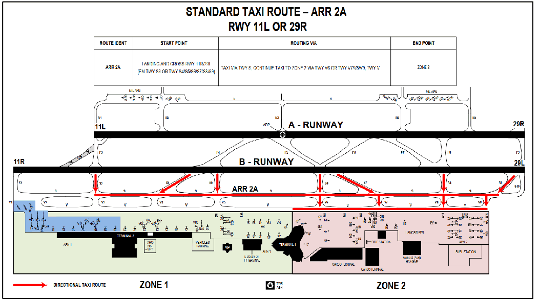
Note: In order to provide information to the pilots about which of TWY V is used for taxi out/in the parking Zone, ATC will immediately assign an exit TWY (Exit Vx) or an entry TWY (Entry Vx) when issuing clearances to the pilots.
2.5.5 Phraseologies in use
2.5.5.1 For departing aircraft
-
When approved Pushback Procedure:
| (Aircraft callsign) pushback approved to face [direction], exit Vx |
Note: Add phrase “exit Vx” to navigate aircraft taxiing out from Zone.
Ví dụ: HVN123, pushback approved to face [direction], exit V3.
-
When issuing Taxi clearance:
| (Aircraft callsign) TAXI TO HOLDING POINT RUNWAY (number) VIA STR name. |
Example: Aircraft at stands 20 belongs to Zone 1 taxiing to the holding point of RWY 11R for departure.
| GCU ATC: HVN123, TAXI TO HOLDING POINT RUNWAY 11R VIA DEP 1B. |
2.5.5.2 For arriving aircraft
| TWR ATC: (Aircraft callsign), vacate Runway via (taxiway), (cross runway (number)) to taxiway (number), contact Ground 121.9 MHz. |
| GCU ATC: (Aircraft callsign) TAXI TO STAND (number) VIA STR name, entry Vx |
Note: Add phrase “entry Vx” to navigate aircraft taxiing to Zone.
Example: Aircraft vacate RWY 11L via TWY P8, cross RWY 11R to S8, taxi via S, V7, V to stand 36.
| TWR ATC: HVN236 Vacate Runway via P8, cross runway 11R to S8, contact Ground 121.9 MHz. |
| GCU ATC: TAXI TO STAND 37 VIA ARR 1A, entry V5 |
2.5.5.3 Change or cancel STR
Upon issuance of STR, when taxiing due to air traffic reasons resulting in the change or cancellation of the issued STR, ATC must cancel the issued STR and issue new taxi clearances using specified different TWYs.
| (Aircraft callsign) CANCEL STR name, TAXI VIA (specific taxiway). |
Example: Aircraft are taxiing via STR DEP 1B for departure RWY 11R (taxi out via V3) when a problem arises. GCU ATC proactively cancels the clearance to follow STR and issues new taxi clearance using another route.
| GCU ATC: HVN123 CANCEL DEP 1B, TAXI VIA (TAXIWAY) V, V5, S, S1 TO HOLDING POINT RWY 11R. |
2.5.6 Charts of STR
There are 4 STRs designed which correspond to the common STR used for departure and arrival aircraft at Noi Bai International Airport when using RWY 11L/29R for landing and RWY 11R/29L for take-off.
VVNB AD 2.21 NOISE ABATEMENT PROCEDURES
NIL
VVNB AD 2.22 FLIGHT PROCEDURES
1 Low visibility procedures (LVP)
1.1 Purpose
Low visibility procedures (LVP) are those applied to ensure the safety, regularity and efficiency of the activities conducted in the movement area at the Noi Bai International Airport in the low visibility conditions.
1.2 Scope and applied subject
LVP is applied to Noi Bai APP, Noi Bai TWR, Noi Bai Aerodrome Meteorological Centre, facilities maintenance unit, serving the two RWYs operation, pilots, aircraft operators and organisations, individuals relating to low visibility operation at Noi Bai International Airport.
1.3 General regulations
1.3.1 Permission/Authorization of Civil Aviation Authority of Viet Nam (CAAV)
-
Domestic and international airlines, who wish to conduct ILS CAT II operation at international airports in Viet Nam, shall submit permission application letter to the CAAV for approval or recognition of ILS CAT II operation prior to execute such operation.
-
The application submitted to CAAV includes name of the operator, aircraft type and registration, a copy of aircraft type certificate document and pilots’ approval for ILS CAT II operations issued by the relevant Authority of the State of Operator (applied for international airlines).
-
When being permitted or authorised for operating conditions by CAAV, pilots shall comply with CAT II operating standard and these operational procedures; proactively and immediately notify Noi Bai APP, Noi Bai TWR unit in case CAT II operating standard is not met.
1.3.2 Applicable standards in condition of low visibility
1.3.2.1 Preparation of low visibility procedures application: When the weather condition at Noi Bai international airport appear at least one of the following conditions:
-
RVR at RWY touchdown zone (11R station), or RWY Mid-point (MID station) fall at 1 200 M or less and tends to decrease; and/or
-
Ceiling (BKN or above) on the cloud altimeter of RWY 11R (sky 11R index displayed on the AWOS AVIMET Noi Bai terminal) is at or below 300 ft (90 M).
-
When the sky is dark, clouds cannot be observed and AWOS can provide vetical VIS (VVnnn), applies to criteria VV is at or below 300FT (90M).
1.3.2.2 Commencement of low visibility procedures application: When the weather condition at Noi Bai international airport appear at least one of the following conditions:
-
RVR at touchdown zone (11R station), or RWY Mid-point (MID-station) fall at 900 m or less; and/or
-
Ceiling (BKN or above) on the cloud altimeter of RWY 11R (sky 11R index displayed on the AWOS AVIMET Noi Bai terminal) fis at or below 250 ft (75 M).
-
When the sky is dark, clouds cannot be observed and AWOS can provide vetical VIS (VVnnn), applies to criteria VV is at or below 250 ft (75 M).
1.3.2.3 Termination of LVP: This is established when the weather conditions at Noi Bai international airport are higher than values specified in 1.3.2.1 and stable in 15 minutes tends to be improved.
1.3.3 Approach procedures in low visibility conditions (LVP):
Implementing approach procedures in compliance with current aerodrome operating minima.
1.4 Operating procedure in condition of low visibility
1.4.1 Approach control procedure
1.4.1.1 During the implementation of LVP, Noi Bai APP, Noi Bai TWR shall continuously update the following information:
-
Operational status of ILS system;
-
Operational status of visual aids system;
-
RVR at 11R station and MID-station;
-
Ceiling at THR of RWY 11R (11R station).
1.4.1.2 In addition to schedule information, on initial contact or as soon as possible thereafter, Noi Bai APP shall provide to arriving aircraft the following information:
-
Current RVR RWY 11R (11R station);
-
RVR at MID point if RVR RWY 11R is below 550 M;
-
Ceiling at THR of RWY 11R (11R station) is below 200 ft (60 M);
-
Unserviceable status of any component of equipments serving CAT II operation, which is not notified in the previous ATIS broadcast.
1.4.1.3 The appropriate separation must be applied between landing aircraft to ensure that landing clearance can be passed to the aircraft before it reaches 2 NM from touchdown. In case of departing aircraft taking off between two landing aircraft, the separation need to be increased appropriately.
1.4.1.4 Speed control shall not be applied to aircraft which is conducting intermediate or final approach for ILS CAT II RWY 11R.
1.4.1.5 8 NM minima separation shall be applied between a preceding departing aircraft and a succeeding landing aircraft, i.e a departing aircraft starts rolling for take-off before to the other landing one reaches 8 NM from touchdown.
1.4.1.6 ILS CAT II approach procedure for RWY 11R is only applied when operating conditions of CAT II are met and aircraft is certified/recognized for CAT II operations by CAAV.
1.4.2 Aerodrome control procedure
1.4.2.1 Landing clearance should be passed to the aircraft before it reaches a distance of 2 NM from touchdown, in case of an unsuccessful approach, ATC advise aircraft to execute a missed approach.
1.4.2.2 Using appropriate taxiways to quickly vacate sensitive area of ILS/LLZ 11R. Landing clearance shall not be issued until:
-
Preceding landing aircraft has vacated LLZ sensitive area;
-
Preceding departure aircraft has airborne and passed the LLZ antenna peak.
1.4.2.3 Personnel, aircraft and vehicles shall not permit to enter LLZ 11R sensitive area in front of the approaching aircraft while the aircraft is within a distance of 2 NM from touchdown until the deceleration is completed.
1.4.2.4 For departing aircraft in CAT II conditions: Personnel, aircraft and vehicles shall not permit to enter LLZ 11R sensitive area in front of departing aircraft when aircraft is received the take-off clearance until its airborned and passed the LLZ antenna peak.
1.4.2.5 Departure and arrival aircraft shall not be cleared to stop, hold or move into the ILS 11R critical/sensitive area when there is an aircraft is approaching to land.
1.4.2.6 Taxi tracks are used in LVP in order to support pilots in verification of aircraft’s position on the ground during LVP operation.
1.4.2.7 Immediately implementing emergency procedures in case of radio communication failure or the aircraft’s current position is not displayed on surface movement radar.
1.4.3 Aerodrome control movement procedure
1.4.3.1 Taxiing instructions and information related to air traffic operation shall be provided to pilots briefly, sufficiently and clearly; pilots shall read back taxiing clearance, avoid hearing unclearly or misunderstanding the clearance. Enhance observing of aircraft and vehicles moving process to ensure that pilots strictly follow ATC instructions/clearance.
1.4.3.2 Monitoring aircraft approaching to land and requesting aircraft quickly vacating RWY and ensure that aircraft do not stop within LLZ 11R sensitive area that causes downgrade ILS (CAT) operation for the following landing aircraft.
1.4.3.3 During LVP operation, follow-me car service shall be provided for landing aircraft and for take-off aircraft (on request).
1.4.3.4 Aerodrome control movement procedures in LVP.
1.4.3.4.1 For take-off aircraft
a) RWY 11R
-
For stands from 8 to 58, 1H, 2H, 3H, 9H: Aircraft from stand → TWY V → TWY V2/V3/V4/V5/V6/V7 → TWY S → TWY S1 → RWY 11R for departure.
-
For stands from 71 to 86:
-
Aircraft from stand → TWY V → TWY V8/V9 → TWY S → TWY S1 → RWY 11R for departure.
-
Aircraft from stand → TWY V → TWY V8/V9 → TWY S → TWY V3/V4/V5/V6/V7 → TWY V → TWY V2/V3/V4/V5/V6 → TWY S → TWY S1 → RWY 11R for departure.
-
b) RWY 11L
-
For stands from 8 to 58, 1H, 2H, 3H, 9H:
-
Aircraft from stand → TWY V → TWY V2/V3/V4/V5/V6/V7 → TWY S → TWY S3 → cross RWY 11R/29L → TWY P3 → RWY 11L for departure.
-
Aircraft from stand → TWY V → TWY V2/V3/V4/V5/V6/V7 → TWY S → TWY S6/S8 → RWY 11R/29L → TWY P5/P6/P7/P8 → RWY 11L/29R → backtrack 180° at the beginning of RWY 11L → RWY 11L for departure (apply for aircraft up to code C and equivalent).
-
-
For stands from 71 to 86:
-
Aircraft from stand → TWY V → TWY V8/V9 → TWY S → TWY S3 → cross RWY 11R/29L → TWY P3 → RWY 11L for departure.
-
Aircraft from stand → TWY V → TWY V8/V9 → TWY S → TWY V3/V4/V5/V6/V7 → TWY V → TWY V2/V3/V4/V5/V6 → TWY S → TWY S3 → cross RWY 11R/29L → TWY P3 → RWY 11L for departure.
-
Aircraft from stand → TWY V → TWY V8/V9 → TWY S → TWY S6/S8 → RWY 11R/29L → TWY P5/P6/P7/P8 → RWY 11L/29R → backtrack 180° at the beginning of RWY 11L → RWY 11L for departure (apply for aircraft up to code C and equivalent).
-
c) RWY 29L
-
For stands from 8 to 58, 1H, 2H, 3H, 9H: Aircraft from stand → TWY V → TWY V2/V3/V4/V5/V6/V7 → TWY S → TWY S9/S10 → RWY 29L for departure.
-
For stands from 71 to 86: Aircraft from stand → TWY V → TWY V8/V9 → TWY S → TWY S9/S10 → RWY 29L for departure.
d) RWY 29R
-
For stands from 8 to 58, 1H, 2H, 3H, 9H:
-
Aircraft from stand → TWY V → TWY V2/V3/V4/V5/V6/V7 → TWY S → TWY S9/S10 → cross RWY 11R/29L → TWY P9 → RWY 29R for departure.
-
Aircraft from stand → TWY V → TWY V2/V3/V4/V5/V6/V7 → TWY S → TWY S6/S8 → RWY 11R/29L → TWY P5/P6/P8 → RWY 11L/29R → backtrack 180° at the beginning of RWY 29R → RWY 29R for departure (apply for aircraft up to code C and equivalent).
-
-
For stands from 71 to 86:
-
Aircraft from stand → TWY V → TWY V8/V9 → TWY S → TWY S9/S10 → cross RWY 11R/29L → TWY P9 →RWY 29R for departure.
-
Aircraft from stand → TWY V → TWY V8/V9 → TWY S → TWY S6/S8 → RWY 11R/29L → TWY P5/P6/P8 → RWY 11L/29R → backtrack 180° at the beginning of RWY 29R → RWY 29R for departure (apply for aircraft up to code C and equivalent).
-
e) From the intersection of RWY 11R and TWY S3
-
For stands from 8 to 58, 1H, 2H, 3H, 9H: Aircraft from stand → TWY V → TWY V2/V3/V4/V5/V6/V7 → TWY S → TWY S3 → the intersection of RWY 11R and TWY S3 for departure.
-
For stands from 71 to 86:
-
Aircraft from stand → TWY V → TWY V8/V9 → TWY S → TWY S3 → the intersection of RWY 11R and TWY S3 for departure.
-
Aircraft from stand → TWY V → TWY V8/V9 → TWY S → TWY V4/V5/V6/V7→ TWY V → TWY V2/V3/V4/V5/V6 → TWY S → TWY S3 → the intersection of RWY 11R and TWY S3 for departure.
-
f) From the intersection of RWY 29L and TWY S8
-
For stands from 8 to 58, 1H, 2H, 3H, 9H: Aircraft from stand → TWY V → TWY V2/V3/V4/V5/V6/V7 → TWY S → TWY S8 → the intersection of RWY 29L and TWY S8 for departure.
-
For stands from 71 to 86: Aircraft from stand → TWY V → TWY V8/V9 → TWY S → TWY S8 → the intersection of RWY 29L and TWY S8 for departure.
g) From the intersection of RWY 29R and TWY P8
-
For stands from 8 to 58, 1H, 2H, 3H, 9H: Aircraft from stand → TWY V → TWY V2/V3/V4/V5/V6/V7 → TWY S → TWY S8 → cross RWY 11R/29L → TWY P8 → the intersection of RWY 29R and TWY P8 for departure.
-
For stands from 71 đến 86: Aircraft from stand → TWY V → TWY V8/V9 → TWY S → TWY S8 → cross RWY 11R/29L → TWY P8 → the intersection of RWY 29R and TWY P8 for departure.
1.4.3.4.2 For landing aircraft
a) RWY 11R
-
For stands from 8 to 10:
-
Aircraft after landing → TWY S5/S6/S7/S8/S9/S10 → TWY S → stands 9, 10 or continue taxiing via TWY V1 → stand 8.
-
Aircraft after landing → TWY S5/S6/S7/S8/S9/S10 → TWY S → TWY V3/V4/V5/V6/V7 → TWY V → TWY V2/V3/V4/V5/V6 → TWY S → stands 9, 10 or continue taxiing via TWY V1→ stand 8.
-
-
For stands from 11 to 58, 1H, 2H, 3H, 9H: Aircraft after landing → TWY S5/S6/S7/S8/S9/S10 → TWY S → TWY V2/V3/V4/V5/V6/V7 → TWY V → stand.
-
For stands from 71 to 86:
-
Aircraft after landing → TWY S5/S6/S7/S8/S9/S10 → TWY S → TWY V8/V9 → TWY V → stand.
-
Aircraft after landing→TWY S5/S6 →TWY S →TWY V5/V6 → TWY V → TWY V6/V7 → TWY S → TWY V8/V9 → TWY V → stand.
-
b) RWY 11L
-
For stands from 8 to 10:
-
Aircraft after landing→TWY P5/P6/P7/P8/P9 → cross RWY 11R/29L → TWY S6/S7/S8/S9/S10 → TWY S → stands 9, 10 or continue taxiing via TWY V1 → stand 8.
-
Aircraft after landing→TWY P5/P6/P7/P8/P9 → cross RWY 11R/29L → TWY S6/S7/S8/S9/S10 → TWY S → TWY V3/V4/V5/V6/V7 → TWY V → TWY V2/V3/V4/V5/V6 → TWY S → stands 9, 10 or continue taxiing via TWY V1 → stand 8.
-
-
For stands from 11 to 58, 1H, 2H, 3H, 9H: Aircraft after landing → TWY P5/P6/P7/P8/P9 → cross RWY 11R/29L → TWY S6/S7/S8/S9/S10 → TWY S → TWY V2/V3/V4/V5/V6/V7 → TWY V → stand.
-
For stands from 71 to 86:
-
Aircraft after landing →TWY P5/P6/P7/P8/P9 → cross RWY 11R/29L → TWY S6/S7/S8/S9/S10 → TWY S → TWY V8/V9 → TWY V → stand
-
Aircraft after landing → TWY P5/P6 → cross RWY 11R/29L → TWY S6 → TWY V6 → TWY V → TWY V7 → TWY S → TWY V8/V9 → TWY V → stand.
-
c) RWY 29L
-
For stands from 8 to 10:
-
Aircraft after landing →TWY S1/S3/S4/S5/S6 →TWY S → stands 9, 10 or taxi via TWY V1 → stand 8.
-
Aircraft after landing → TWY S3/S4/S5/S6 → TWY S → TWY V3/V4/V5/V6/V7 → TWY V → TWY V2/V3/V4/V5/V6 → TWY S → stands 9, 10 or taxi via TWY V1 → stand 8.
-
-
For stands from 11 to 58, 1H, 2H, 3H, 9H: Aircraft after landing → TWY S1/S3/S4/S5/S6 → TWY S → TWY V2/V3/V4/V5/V6/V7 → TWY V → stand.
-
For stands from 71 to 86:
-
Aircraft after landing →TWY S1/S3/S4/S5/S6 → TWY S → TWY V8/V9 → TWY V → stand.
-
Aircraft after landing→TWY S1/S3/S4/S5/S6 →TWY S → TWY V2/V3/V4/V5/V6 → TWY V → TWY V3/V4/V5/V6/V7→ TWY S → TWY V8/V9 → TWY V → stand.
-
d) RWY 29R
-
For stands from 8 to 10:
-
Aircraft after landing → TWY P3/P4/P5/P6 → cross RWY 11R/29L → TWY S3/S4/S5/S6/S7 → TWY S → stands 9, 10 or taxi via TWY V1 → stand 8.
-
Aircraft after landing → TWY P3/P4/P5/P6 → cross RWY 11R/29L → TWY S3/S4/S5/S6/S7 → TWY S → TWY V3/V4/V5/V6/V7 → TWY V → TWY V2/V3/V4/V5/V6 → TWY S → stands 9, 10 or taxi via TWY V1 → stand 8.
-
-
For stands from 11 to 58, 1H, 2H, 3H, 9H: Aircraft after landing → TWY P3/P4/P5/P6 → cross RWY 11R/29L → TWY S3/S4/S5/S6/S7 → TWY S → TWY V2/V3/V4/V5/V6/V7 → TWY V → stand.
-
For stands from 71 to 86:
-
Aircraft after landing → TWY P3/P4/P5/P6 → cross RWY 11R/29L → TWY S3/S4/S5/S6/S7 → TWY S → TWY V8/V9→ TWY V → stand.
-
Aircraft after landing → TWY P3/P4/P5/P6 → cross RWY 11R/29L → TWY S3/S4/S5/S6/S7 → TWY S → TWY V2/V3/V4/V5/V6 → TWY V → TWY V3/V4/V5/V6/V7 → TWY S → TWY V8/V9 → TWY V → stand.
-
1.4.3.5 The critical and sensitive area charts of ILS CAT I - RWYs 11R, 29L, 11L, 29R and ILS CAT II - RWY 11R
-
Critical and sensitive area of ILS CAT I - RWY 11R.
LOCALIZER 11R CAT I
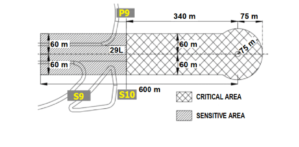
GLIDE PATH 11R CAT I
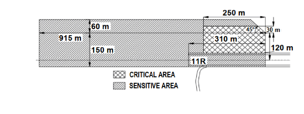
-
Chart of the critical and sensitive area of ILS CAT II - RWY 11R.
LOCALIZER 11R CAT II
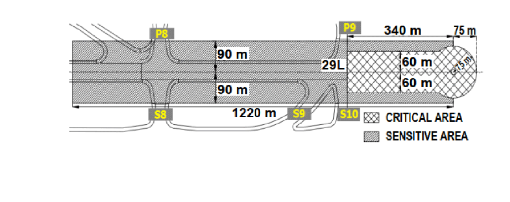
GLIDE PATH 11R CAT II
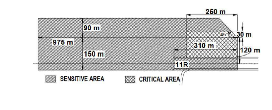
-
Chart of the critical and sensitive area of ILS CAT I - RWY 29L.
LOCALIZER 29L CAT I
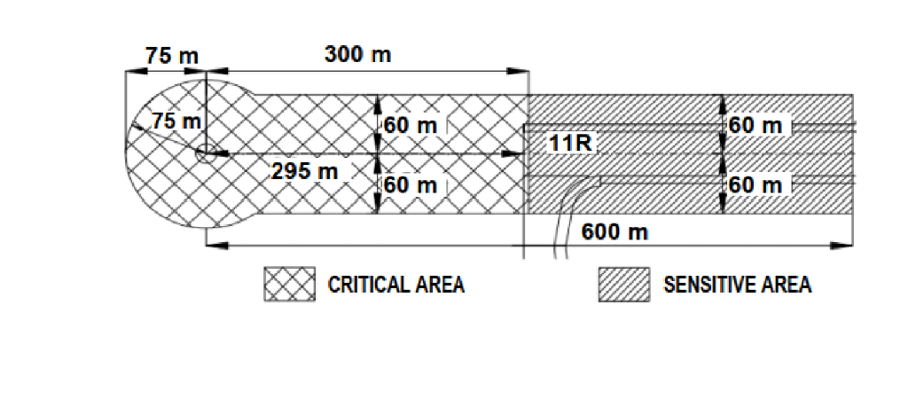
GLIDE PATH 29L CAT I
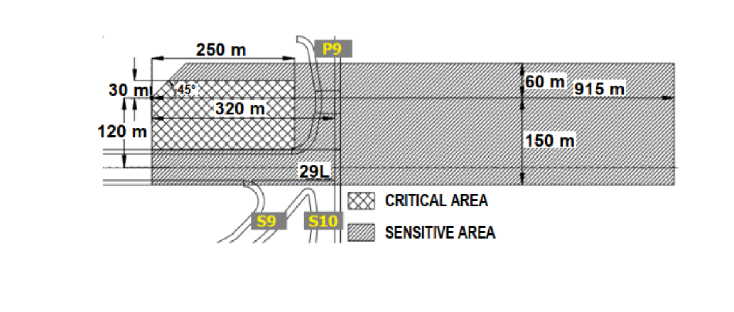
-
Chart of the critical and sensitive area of ILS CAT I - RWY 11L.
LOCALIZER 11L CAT I
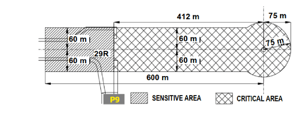
GLIDE PATH 11L CAT I
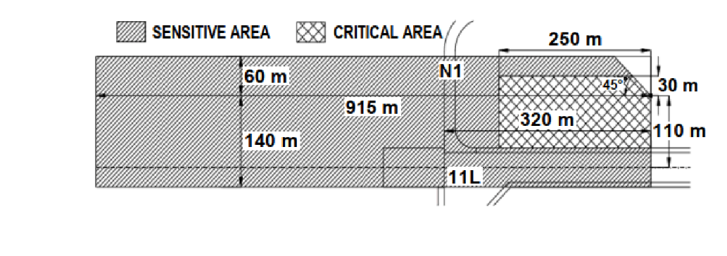
-
Chart of the critical and sensitive area of ILS CAT I - RWY 29R.
LOCALIZER 29R CAT I
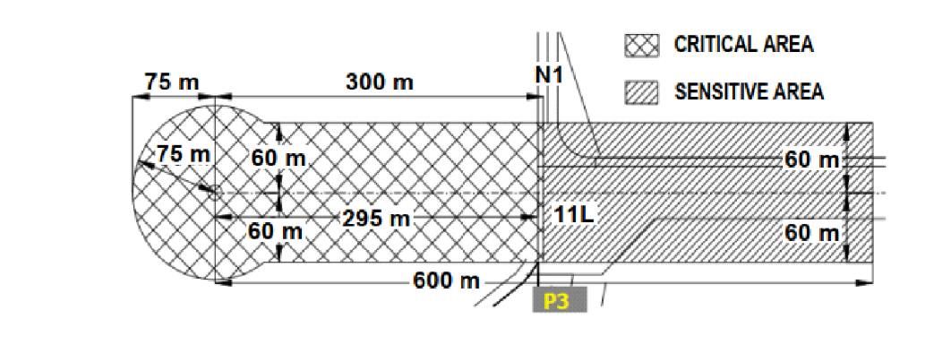
GLIDE PATH 29R CAT I
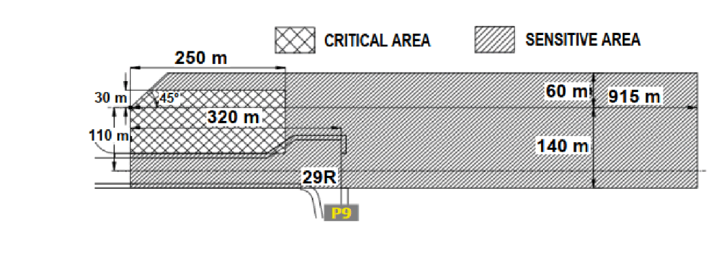
1.4.4 Vehicles movement control
-
Vehicles shall not enter RWY if landing aircraft has reached at 8 NM from touchdown;
-
Vehicles are prohibited within manoeuvring area unless cleared by Noi Bai TWR;
-
Vehicles are not allowed to hold on the positions closer to RWY than the holding position in front of RWY (stop bars lights).
1.5 Implementations in condition of low visibility
1.5.1 When weather condition decreases to LVP:
-
Timely inform to pilots to suspend or do not apply ILS CAT II approach procedures;
-
Ensure to broadcast the phrase "LOW VISIBILITY PROCEDURES IN OPERATION" on ATIS.
1.5.2 When appear "decrease" component in ILS CAT II operation standard:
-
When ILS CAT II can not be applied, Noi Bai TWR must immediately inform to related aircraft, Noi Bai APP and apply appropriate flight operation procedures in accordance with regulations;
-
Noi Bai TWR, Noi Bai APP unit reports to related aircraft and apply appropriate flight operation procedures in accordance with regulations;
-
Timely inform to pilots about applying or do not applying ILS CAT II approach procedures.
1.6 Handling abnormal, emergency situations
In abnormal/emergency situations, related units shall strictly co-ordinate with each other in handling situations, give priority to aircraft in urgency, select the most appropriate flight procedure and RWY to ensure the safety of flight as well as support ground services on request of pilots and in accordance with current regulations;
Suspend other activities if necessary to give priority to aircraft in urgency.
1.7 Application condition of low visibility
LVP application will be implemented if there are requirements for flight operations, with standard weather conditions in item 1.3.2.2 of these procedures and the operational components in LVP at Noi Bai international airport meet minimum standards as follows:
1.7.1 For ILS/DME system runway 11R:
-
Primary and secondary of Localizer (LLZ), Glidepath (GP), DME are normally operated;
-
All of Localizer (LLZ), Glidepath (GP) and DME monitors are normally operated;
-
There is no deviation between two of three devices (LLZ, GP, DME) can lead to device's warning;
-
ILS/DME remote system is normally operated.
1.7.2 For lighting system runway 11R:
Approach lighting systems:
-
Within the range of 450 M (from THR of RWY 11R THR): More than 95% of approach lighting systems are operated, and not any two consecutive lights are unserviceable;
-
Outside the range of 450 M (from THR of RWY 11R): More than 85% of approach lighting systems are operated, and not any two consecutive lights are unserviceable.
RWY centre line lights, RWY edge lights, THR of RWY lights: More than 95% of lights are operated, and not any two consecutive lights are unserviceable;
Touchdown zone lights system: More than 90% of lights are operated, and any two consecutive lights are unserviceable;
RWY end lights system: More than 70% of lights are operated, and any two consecutive lights are unserviceable;
Stop bars lights system: More than 95% of lights are operated, and any two consecutive lights are unserviceable.
1.7.3 For RVR system, ceiling measuring ceilometers:
RVR system and ceiling measuring ceilometers operate normally; RVR values at RWY 11R station, mid station and ceiling shall be directly indicated at working position of Noi Bai TWR, Noi Bai APP.
1.7.4 For power supply system:
Electric power source for lighting system shall be provided by UPS - or by using electric generator as the primary source of power supply, using the grid supply as the secondary power supply.
1.7.5 For ILS critical/sensitive area:
Personnel and vehicles are not allowed to operate within ILS critical and sensitive areas.
1.7.6 For airport emergency forces:
Airport emergency services, facilities and equipments ensure meeting CAT 9 requirements for rescue and firefighting and are available to cope with urgency following the current emergency procedures.
Note: In case LVP is applied and weather conditions are good enough to operate ILS CAT I but ILS CAT II does not meet the standards (due to technical or facilities failure and maintenance team can immediately revert to normal operation), LVP application is continued.
2 OPERATIONAL PROCEDURES FOR RNAV 1 SID/STAR
2.1 General
In order to operate RNAV 1 SID/STAR procedures at Noi Bai Aerodrome, the aircraft navigation system shall meet ICAO RNAV 1 standard of accuracy based on GNSS infracstructure.
Pilots, ATS personal and the related personnel are responsible for checking RAIM Prediction in accordance with operational procedure for RAIM Prediction Service.
Aircraft operators/pilots who are not authorized to fly RNAV 1 procedures based on GNSS shall inform Air traffic controller (ATC) and expect to use conventional procedures in accordance with actual conditions.
The transition routes have been established to connect RNAV 1 SID/STAR with the existing ATS routes.
2.2 Operational procedure
Aircraft operators/pilots expecting to use RNAV 1 SID/STAR procedures at Noi Bai Aerodrome shall fill appropriate navigation capability indicators in flight plan, as follows:
-
Insert R (PBN approved) into Item 10a.
-
Inserting D1 (RNAV 1 all permitted sensors) or D2 (RNAV 1 GNSS) after PBN/.... in Item 18.
-
Specify equipment to support each type of navigation capability in Item 18 and insert them into Item 10a (G, D, I for D1 or G for D2).
Before implementation of flights, pilots must verify that the navigation database is updated to current time and verify that the aircraft position has been entered correctly. Pilots must confirm the entry and exit points on the ATS route assigned on initial clearance and any subsequent changes of route, ensuring the waypoints sequence depicted by their navigation system matches the route depicted on the appropriate chart(s) and their assigned route.
Pilots must not fly a RNAV 1 SID/STAR unless it is retrievable by procedure from the on-board navigation database and conforms to the charted procedure (this procedure may subsequently be modified in response to ATC clearances). The manual entry, or creation of new waypoints by inserting latitude/longitude or rho/theta values is not permitted. Additionally, pilots must not change any RNAV 1 SID/STAR database waypoint type from a fly-by waypoint to a fly-over waypoint or vice versa.
Conditions for applying RNAV 1 SID/STAR at Noi Bai: ATS surveillance is mandatory.
ATC shall maintain monitoring aircraft when it conducts RNAV 1 SID/STAR. Pilots are expected to maintain route centrelines during all RNAV 1 operations unless authorized to deviate by ATC or under emergency conditions.
Pilots shall comply with altitude assigned by ATC, as well as adhere to the altitude and speed restrictions depicted on the cleared RNAV 1 SID/STAR, unless there are other clearance by ATC.
In case ATC assigns the aircraft not to conduct the expected procedure, the pilots should not modify the flight plan in the system until a clearance to rejoin the procedure is received or the ATC confirms a new procedure clearance.
During the operation of the RNAV 1 SID/STAR, ATC and pilots apply the standard phraseology specified in Doc 4444 PANS–ATM – ICAO, Procedures For Air Navigation Services – Air Traffic Management.
Conventional SIDs/STARs and radar vectoring still applied to aircraft that are not approved for RNAV 1 and other aircraft depending on traffic situation.
2.3 For departing aircraft
The procedures for departing aircraft include 2 main elements:
-
SID; and
-
Transition route if necessary.
A transition route starts at the last point of SID to a position from which the aircraft will intercept the ATS route.
Altitude restrictions are designed to establish the separation between departing aircraft and obstacles as well as arriving aircraft.
ATC shall issue a clearance for departing aircraft including the following contents:
-
Call sign;
-
Clearance limit, normally destination aerodrome;
-
SID and transition route if necessary;
-
Route;
-
Assigned flight level/altitude;
-
SSR code; and
-
Any other related and necessary instruction or information not contained in the SID description.
Note: In case a clearance provided SID is not assigned altitude/flight level, the pilots are not allowed to reach the altitude/flight level itself on the SID vertical profile. Pilots shall re-confirm with ATC to assign a specified altitude/flight level to ensure flight safety.
2.4 For arriving aircraft
The procedures for arriving aircraft include 2 main elements:
-
Transition route if necessary; and
-
STAR.
A transition route starts from a waypoint on the ATS route to the position that starts the STAR.
Altitude restrictions are designed to establish the separation between arriving aircraft and obstacles as well as departing aircraft.
Approach clearances shall be issued by ATC in accordance with actual operating conditions.
ATC shall issue clearance for arriving aircraft including the following contents:
-
Call sign;
-
STAR and transition route if necessary;
-
Runway-in-use;
-
Cleared flight level/altitude; and
-
Any other related and necessary instruction or information not contained in the STAR description.
Note: In case a clearance provided STAR is not assigned altitude/flight level, the pilots are not allowed to reduce the altitude/flight level itself on the STAR vertical profile. Pilots shall re-confirm with ATC to assign a specified altitude/flight level to ensure flight safety.
2.5 Contingency procedure
2.5.1 Aircraft is unable to comply with RNAV 1 requirement
If aircraft is unable to comply with RNAV 1 requirements, pilots shall inform ATC immediately and expect to be used the conventional procedure in accordance with actual conditions.
2.5.2 Aircraft degrade the RNAV capability or failure of GNSS signal
When the aircraft degrade the RNAV 1 capability or fail in GNSS signal, which leads to the inability to comply with the requirements of RNAV 1, pilots must advise ATC immediately and expect to be used the conventional procedure in accordance with actual conditions.
2.5.3 Aircraft experience bad weather
When an aircraft flying on RNAV 1 procedures encounters bad weather which is likely to impact the aircraft’s adherence to the cleared flight procedures, pilots will notify ATC and request a revised clearance. ATC clearance "Direct to" will be used for aircraft to avoid bad weather where applicable. In case bad weather area affects important points of RNAV 1 procedures, radar vector shall be applied by ATC for all aircraft.
2.5.4 Radio communications failure procedure
In case of a radio communication failure, the pilots are expected to proceed the following procedures:
-
Set transponder to Mode A/C, code 7600;
-
Arriving aircraft continue flying on the assigned STAR procedure, complying with the altitude and speed restrictions and at the end of the STAR make appropriate approach procedures;
-
Departing aircraft continue flying on the assigned SID procedure, complying with the altitude and speed restrictions, climb to cruising level as mentioned in the current flight plan.
2.5.5 ATS surveillance failure procedure
ATC implement processing method according to the operating procedure specified in the operations manual of ATS unit.
ATC expect to apply non-radar procedural control for all aircraft until ATS surveillance system resumes normal operation.
2.5.6 Procedure for changing runway-in-use
ATC shall assign time to conduct the change of the runway-in-use, determine aircraft sequence corresponding to the runway-in-use to notify and issue the assigned clearance for RNAV 1 SID/STAR procedures which are suitable for the pilots.
In case of necessity, ATS surveillance vectoring may be used by ATC to deal with complicated situations.
3 RNAV 1 SID/STAR WAYPOINTS
|
STT |
Tên lộ điểm |
Tọa độ (WGS-84) |
Ghi chú |
|---|---|---|---|
|
Number |
Waypoints |
Coordinates (WGS-84) |
Remarks |
| 1 | RW11L | 211330.95N 1054733.25E | THR |
| 2 | RW11R | 211328.91N 1054710.85E | THR |
| 3 | RW29L | 211252.52N 1054916.77E | THR |
| 4 | RW29R | 211300.28N 1054919.32E | THR |
| 5 | BANCO | 212954.2N 1055758.5E | |
| 6 | BISON | 202559.9N 1053829.8E | |
| 7 | BQ | 211254.0N 1040217.0E | NAVAID |
| 8 | KHARO | 210046.8N 1051422.3E | |
| 9 | BUNBO | 214226.1N 1061948.1E | |
| 10 | DALAI | 212208.1N 1053901.2E | |
| 11 | DENMO | 220229.8N 1062452.2E | |
| 12 | DIHAI | 214954.0N 1060748.8E | |
| 13 | DILEN | 220635.4N 1052812.6E | |
| 14 | DONMO | 211037.7N 1053515.4E | |
| 15 | FINAM | 203307.1N 1055936.2E | |
| 16 | HAKAO | 214355.0N 1061610.0E | |
| 17 | HOBIN | 204100.4N 1053820.2E | |
| 18 | HUVAN | 211230.0N 1050641.0E | |
| 19 | JULUN | 214518.7N 1052402.5E | |
| 20 | KUNHI | 211732.2N 1055457.3E | |
| 21 | LENNU | 212019.0N 1050728.2E | |
| 22 | LIMIN | 213539.3N 1060604.3E | |
| 23 | MC | 204941.0N 1044201.0E | NAVAID |
| 24 | MIMON | 205032.6N 1053815.7E | |
| 25 | MUCHI | 205643.5N 1050252.8E | |
| 26 | NAH | 202314.0N 1060704.0E | NAVAID |
| 27 | NAKHA | 215800.0N 1062936.0E | |
| 28 | NUCOC | 213321.9N 1054533.9E | |
| 29 | SONTA | 210121.7N 1053810.5E | |
| 30 | SUDON | 212302.2N 1054901.2E | |
| 31 | TAMDA | 214922.3N 1053055.8E | |
| 32 | THOLA | 214421.6N 1054152.6E | |
| 33 | TINLY | 203436.1N 1060458.0E | |
| 34 | XARIS | 210105.2N 1052638.6E | |
| 35 | XUNBI | 210445.7N 1050736.5E | |
| 36 | NB110 | 211002.7N 1055932.9E | |
| 37 | NB111 | 205734.1N 1055807.5E | |
| 38 | NB112 | 211905.0N 1060232.0E | |
| 39 | NB113 | 212507.7N 1054151.5E | |
| 40 | NB114 | 205305.7N 1054527.6E | |
| 41 | NB290 | 211815.4N 1053036.2E | |
| 42 | NB291 | 212653.3N 1053326.7E | |
| 43 | NB292 | 210937.5N 1052745.8E | |
| 44 | NB293 | 210555.1N 1053226.3E | |
| 45 | NB360 | 211635.6N 1053653.0E | |
| 46 | NB361 | 211622.7N 1053708.2E | |
| 47 | NB362 | 211742.2N 1053231.8E | |
| 48 | NB363 | 211901.6N 1052755.3E | |
| 49 | NB364 | 212020.8N 1052318.7E | |
| 50 | NB365 | 212139.9N 1051842.1E | |
| 51 | NB366 | 211554.3N 1051649.5E | |
| 52 | NB367 | 211435.2N 1052126.3E | |
| 53 | NB368 | 211316.1N 1052602.7E | |
| 54 | NB369 | 211157.0N 1053039.1E | |
| 55 | NB371 | 210050.2N 1051630.4E | |
| 56 | NB372 | 205102.3N 1051930.2E | |
| 57 | NB373 | 204339.2N 1052729.8E | |
| 58 | NB374 | 205001.2N 1051740.0E | |
| 59 | NB375 | 204154.5N 1052626.7E | |
| 60 | NB376 | 203900.6N 1053821.2E | |
| 61 | NB377 | 212725.9N 1052034.6E | |
| 62 | NB378 | 212606.6N 1052511.3E | |
| 63 | NB379 | 212447.2N 1052948.0E | |
| 64 | NB380 | 212327.7N 1053424.6E | |
| 65 | NB381 | 214226.9N 1054231.1E | |
| 66 | NB382 | 214316.9N 1055109.1E | |
| 67 | NB383 | 214053.4N 1055926.7E | |
| 68 | NB384 | 214516.5N 1055121.7E | |
| 69 | NB385 | 214238.9N 1060028.4E | |
| 70 | NB386 | 213653.8N 1060745.2E | |
| 71 | NB451 | 210955.0N 1055930.3E | |
| 72 | NB452 | 210834.9N 1060406.3E | |
| 73 | NB453 | 210714.6N 1060842.1E | |
| 74 | NB454 | 210554.3N 1061317.9E | |
| 75 | NB455 | 210433.8N 1061753.6E | |
| 76 | NB456 | 211002.4N 1055932.9E | |
| 77 | NB462 | 211540.1N 1060124.3E | |
| 78 | NB463 | 211420.0N 1060600.1E | |
| 79 | NB464 | 211259.9N 1061036.2E | |
| 80 | NB465 | 211139.6N 1061512.2E | |
| 81 | NB466 | 211019.2N 1061948.1E | |
| 82 | BIVIM | 193034.0N 1060628.0E | |
| 83 | TOSCA | 194827.0N 1055729.0E | |
| 84 | NB501 | 194438.0N 1054312.0E | |
| 85 | NB502 | 194545.0N 1052720.0E | |
| 86 | NB503 | 195243.0N 1051203.0E |
4 OPERATIONAL PROCEDURE OF AIRPORT COLLABORATIVE DECISION MAKING (A-CDM)
4.1 Purpose
Airport Collaborative Decision Making (A-CDM) is a procedure agreed among units: Airport Operators, Airlines, Ground Handlings, Air Traffic Control, Air Traffic Flow Management to collaboratively make decision at the airport in order to manage the congestion at the airport, increase the efficiency for departure aircraft, optimise the use of resource at the airport, enhance the ability of predicting and implementing exactly the process of a complete flight from departure phase till arrival phase.
All civil flights operating at Noi Bai International Airport must comply to A-CDM operational procedures, except for VIP, emergency, medical, and search and rescue flights.
4.2 Applicable Time frame
Noi Bai International Airport officially implement A-CDM 24/7 for arriving and departing flight from 1701, 31st JAN 2024.
4.3 Operational Procedures
The coordination among flights is based on the principle which flights/aircrafts are best planned shall be served best (Best planned, Best served).
There are two core timestamps of A-CDM procedures: Target Off-Block Time (TOBT) and Target Startup Approval Time (TSAT), which shall be applied during operations at Noi Bai International Airport.
4.3.1 A-CDM Portal description and information update instruction for pilots
A. TOBT and TSAT displays
TOBT and TSAT are displayed on the main interface of A-CDM Portal.
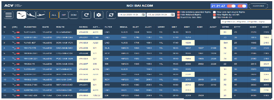
TOBT and TSAT of flights are displayed on the pilot interface of A-CDM Portal.
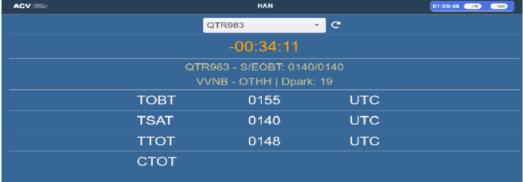
B. Log-in to Pilot Interface of A-CDM Portal
-
Log-in
-
Input address https://acdm.vietnamairport.vn
-
Click “With Email”. Input email and password to login
-
Deselect “Use Password to login” to use login by OTP
-
On default page:
-
Choose NOI BAI
4.3.2 TSAT Countdown Timer for Pilots
4.3.2.1 Overview
TSAT Countdown Timer for Pilot page has the feature to view pilot-specific data fields. These fields are synchronized in real time. These fields include: Callsign, route, SOBT, EOBT, TOBT, TSAT, TTOT, CTOT, Departure Parking (DPRK).
4.3.2.2 Features of TSAT Countdown for Pilot
-
The real-time clock that defaults to UTC. If you want to change to local time, click the "convert toggle" button next to it;
-
Click “Please Select Flight” then choose a flight;
-
When TOBT or TSAT of a flight is updated, FDE will blink for 15 seconds to indicate that the field has been updated.
Note: These flights are scheduled between -2 hours and +3 hours from the current time.
For Countdown Timer: after the Pilot selected a flight, one of these cases will occur:
-
If the selected flight has TSAT, Countdown Timer will be activated and indicated in orange.
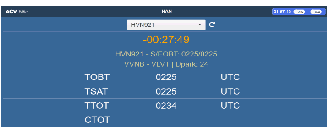
-
Countdown Timer will turn to green when the current time is within TSAT window +/-5 minutes.
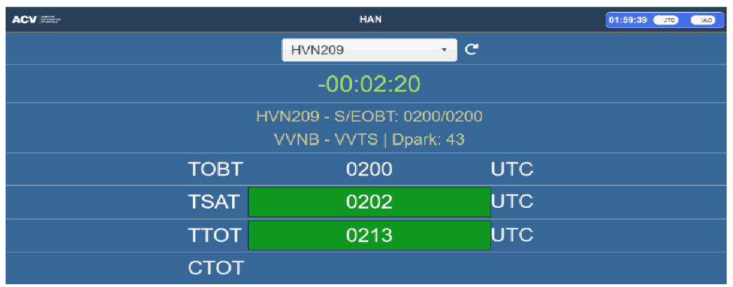
-
Countdown Timer will turn to red when the current time passes TSAT over 5 minutes.
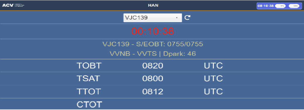
-
If there is AOBT, Countdown Timer will turn to white and stops counting.
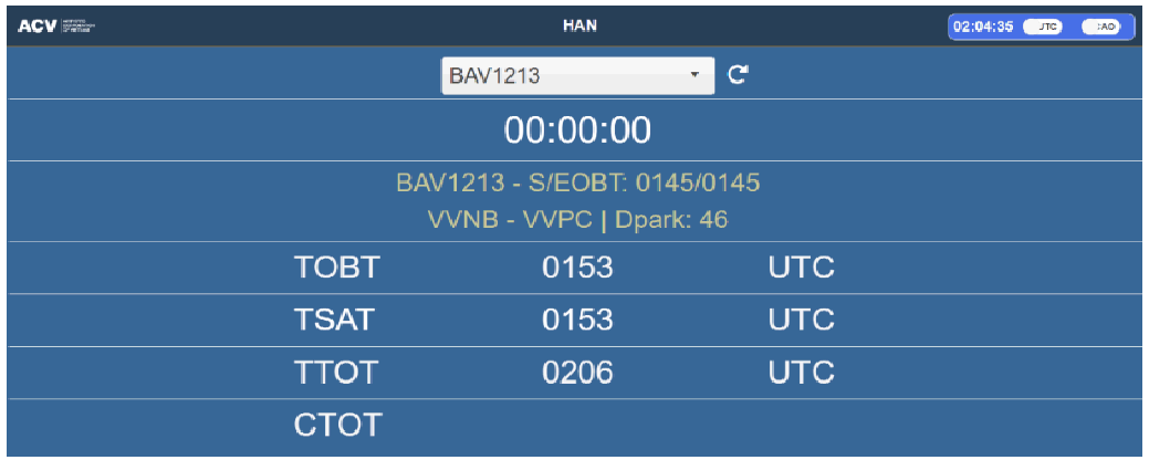
4.3.3 Definition of commonly used terms in A-CDM
-
TSAT (Target Start-Up Approval Time): The time provided by ATC taking into account TOBT and CTOT, that an aircraft can expect to receive start-up /push-back approval (start up and push back approval are issued together).
-
EOBT (Estimated Off-block Time): The estimated time that an aircraft will depart from its parking position.
-
TOBT: The point in time at which the aircraft operator or ground handling estimates an aircraft to be ready: all ground handling activities are finished, the flight preparation in the cockpit has finished, all doors are closed and the boarding bridge and handling equipment removed, push back truck available and ready for immediate start and push back upon clearance from the Tower.
-
ALDT: The actual time that an aircraft touches down on the runway.
-
TTOT: The target time that an aircraft will become airborne from the TRWY, based on TSAT.
-
CTOT: The calculated time for take-off. CTOT is issued by the ATFMC as a result of an ATFM slot allocation and is a constraint in the planning of a TTOT.
4.3.4 Operation Procedures
4.3.4.1 SOBT
Aircraft starts taxi out of the current stand as planned. The leaving time from stand of aircraft is issued based on seasonal flight schedule.
4.3.4.2 EOBT:
Expected time for aircraft to taxi out of the current stand.
Foreign airlines, private flights, charter flights, official duties aircraft without representatives at NIA shall authorize GH to submit flight schedule (including EOBT information) for the next day to the Noi Bai International Airport before 03:00 daily.
In operating day, EOBT will be updated by FPL or DLA messages, as detailed:
-
Proposal FPL will be submitted by Airlines to Noi Bai ARO/AIS Center via AMHS/AFTN or AIS/AIM or email, not later than:
-
150 minutes before EOBT for domestic flights that submit FPL remotely.
-
210 minutes before EOBT for international flights that submit FPL remotely.
-
60 minutes before EOBT when submitting hard copy of Proposal Flight Plan to Noi Bai ARO/AIS Center.
-
-
For flights that depart from airports and airspace of Level 2/ Level 3 Multi-Nodal ATFM Network to airports and airspace of Level 3 Multi-Nodal ATFM, the timing of FPL submission shall comply to the current ATFM Multi-Nodal Operational Procedures of Viet Nam.
-
Upon receiving proposal FPL, Noi Bai ARO/AIS Center is responsible for examining, cross-checking and approving FPL then issuing the approved FPL to stakeholders via ATFN/AMHS or AIS/AIM immediately.
-
Airlines shall notify Noi Bai ARO/AIS Center and ATFMC if new EOBT is available (for the delay from 15 minutes to less than 60 minutes compared to the initial EOBT). Except for flights departing from NoiBai International Airport to airports and airspace of Level 3 Multi-Nodal ATFM Network, ATC Flight plan submission and relevant information about generating ATS message (including DLA, CNL, CHG messages) shall comply to the current Level 2 ATFM Multi-Nodal Operational Procedures of Viet Nam. Noi Bai ARO/AIS Center promulgate DLA message as regulated.
-
Airline shall submit a new proposal FPL and notify Noi Bai ARO/AIS Center and ATFMC if flight delays more than 60 minutes compared to old EOBT.
4.3.4.3 ALDT
ALDT is actual time aircraft touch down on RWY. This time is recorded by Radar NOVA9000 system and from ARR message (AMHS) and then send to A-CDM Portal via SMIS system.
4.3.4.4 TOBT
As soon as a flight schedule is updated into the A-CDM Portal system, the innitial TOBT shall be calculated based on the FPL information and shall be set equal to the SOBT.
Then, based on the FPL submitted by airline, the 1st TOBT will be set equal to EOBT (before the automatically calculated TOBT).
As soon as the estimated landing time of an arrival flight is defined, the 2nd TOBT will be automatically calculated following the formula: The 2nd TOBT = EIBT (ELDT + EXIT) + ETTT.
Changes of ELDT/EIBT will result in updating TOBT.
As soon as the actual landing time of an arrival flight is recorded, the 3rd TOBT will be automatically calculated following the formula: The 3rd TOBT =EIBT(ALDT+EXIT) + ETTT.
This automatic calculation process will continue until the flight is actual arrived at aircraft stand and AIBT is confirmed in the system. The 4th TOBT = AIBT + ETTT.
New TOBTs are always greater or equal to EOBT.
In case of aircraft parking overnight or aircraft swapping, TOBT will be automatically calculated based on ACGT with the formula: TOBT = ACGT + ETTT. GH is responsible for inputing ACGT when the ground-handling activities for the aircraft start as scheduled.
From this point onward, GH is mainly responsible for updating TOBT. The GH will consider available resources and their own planning as well as agreed procedures with airlines in updating TOBT for flights
Upon receiving notices of regulated CTOTs from ATFMC, AO/GH will calculate and adjust new TOBTs in accordance with provided CTOTs. According to actual traffic conditions, ATC will sequence the departure of flights within CTOT timeframes if possible.
Pilot should continue to monitor TOBT to ensure the aircraft is ready within TOBT +/- 5 minutes. If the aircraft readiness is unachievable within TOBT +/- 5 minutes, pilot shall inform GH to update TOBT.
Another source for updates of the TOBT can be the EOBT. If the flight plan EOBT is updated to a later time than the current TOBT, GH needs to update the new TOBT. The number of manual TOBT update will be limited to not more than 3 times within 30 minutes before EOBT.
4.3.4.5 TSAT
TSAT is provided basing on the TOBT, CTOT and/or ATC flow. Base on those factors, aircraft is expected to get approval for starting up engine/pushing back or taxiing.
4.3.4.6 TOTT
TTOT is the target time that an aircraft will become airborne based on TOBT/TSAT and estimated Taxi-Out Time (EXOT).
4.3.5 Start-up Procedures
Start-up procedure is based on a collaborative TSAT planning. Based on the TOBT received by ATC, DMAN system will generate a TSAT.
-
At TSAT: +/-5 minutes, Pilots will request and receive start-up approval from the ATC.
-
TSAT window: +/- 5 minutes from TSAT.
If start-up/push-back clearance requested by pilots is within TSAT window < 6 minutes, (TSAT + ≤ 05 minutes: 59 seconds displaying on the equipment monitor), it is still considered as within TSAT window.
If start-up clearance requested by pilots is within TSAT window, ATC is responsible for issuing start-up/push-back approval clearance if possible.
-
For flights that require idle engine start before starting all engines for departure: Flight crew shall actively estimate the idle engine start time to ensure that the aircraft will start all engines for departure within the Target Start-Up Approval Time (TSAT) window. The flight crew should inform the ground handling (GH) personnel of this information so that they can decide if it is necessary to update the Target Off-Block Time (TOBT) of the flight (note: the idle engine start time should be added).
-
For aircrafts that need to be pushed out before starting all engines for departure: Flight crew shall actively estimate the time to request push-back clearance from ATC. Once the push-back process is completed, the flight crew requests clearance to start all engines. This engine start time should be within the TSAT window. The purpose is to ensure the preservation of the TTOT for the flight.
If start-up/push-back clearance requested by pilots is before TSAT window, ATC shall request pilots to call again for clearance within TSAT window.
If there is no start-up/push-back clearance requested by pilots within TSAT window, then the TSAT of the flight shall be considered expired and will be removed from departure sequence.
If start-up/push-back clearance requested by pilots is after TSAT window, ATC shall not issue start-up/push-back clearance and request related units (Airlines, GH) to update TOBT in order to receive a new TSAT.
In case that ATC is unable to issue engine start-up/push-back clearance within the TSAT window due to certain special reasons such as VIP flights or unfavourable operational conditions, the flight crew will be notified to "standby." Subsequently, ATC will issue a new TSAT for the flight based on the actual operational activities at the airport, ensuring that it does not disrupt the departure sequence of previously allocated aircraft. ATC will then issue engine start/push-back clearance within the adjusted TSAT window and ASAT shall be recorded for data analysis.
Pilots shall check for updates of TOBT, TSAT directly on A-CDM Portal.
In case pilot cannot check for the updates of TOBT, TSAT on A-CDM Portal, he/she shall be responsible for contacting with GH or ATC to receive TSAT via RT/VHF.
4.3.6 Phases of A-CDM flights
4.3.6.1 Planning phase
-
Airlines schedule flights timetable for the next day and submit to Noi Bai Operational Control Centre - Noi Bai International Airport by 0300 previous day.
-
Noi Bai International Airport inserts the next day flight schedule into SMIS system and arrange stands for flights by 1300 previous day. For airlines without representative at the airport, GH shall be responsible for submitting flight schedule to Noi Bai International Airport.
-
Flight is established INI status in the system when airlines send FPL draft to Noi Bai ARO/AIS Center via AMHS/AFTN system or AIS/AIM/email system or submit directly no later than:
-
150 minutes before EOBT for domestic flights that submit FPL remotely.
-
210 minutes before EOBT for international flights that submit FPL remotely.
-
60 minutes before EOBT when submitting hard copy of Proposal FPL to Noi Bai ARO/AIS Center.
-
-
For flights that depart from airports and airspace of Level 2/ Level 3 Multi-Nodal ATFM Network to airports and airspace of Level 3 Multi-Nodal ATFM, the timing of FPL submission shall comply to the current ATFM Multi-Nodal Operational Procedures of Vietnam.
4.3.6.2 Arrival phase
-
Flight is established FIR status in the system 10 minutes after AMAN system automatically sends the first ELDT message to A-CDM Portal.
-
Flight is established FNL status in the system 5 minutes before ELDT, aircraft is at final-approach phase.
-
Flight is established LND status in the system after:
-
Aircraft landing.
-
The time aircraft touches down on RWY is the reference time for ALDT and ALDT message is automatically sent from NOVA9000/SMIS to A-CDM Portal.
-
4.3.6.3 Ground Service Phase
-
Flight is established IBK status in the system when: Aircraft is arrived at stand and GH records AIBT value of the flight.
-
Flight is established BRD status in the system when: GH updates the boarding time of passengers by inserting ASBT in the system or directly input into A-CDM Portal, based on the time the first boarding card is scanned at the boarding gate.
-
Flight is established RDY status in the system when:
-
Ground service is completed;
-
Aircraft is ready when notified by the pilot that the preparation process in the cockpit is completed, all gates are closed, passenger bridge and equipments are removed, tow tractors are ready to tow as soon as receiving TWR clearance. GH directly insert AEGT in the internal system connected to A-CDM Portal or directly insert in A-CDM Portal. During phase 1. AEGT is determined by ARDT.
-
4.3.6.4 Departure phase
-
Flight is established OBK status in the system when:
-
Aircraft taxi out of stand;
-
GH input AOBT in the internal system connected to A-CDM Portal or directly input in A-CDM Portal.
-
-
Flight is established DEP status in the system when:
-
Aircraft takes off from RWY;
-
A-CDM Portal receives ATOT via NOVA9000 or DEP message from SMIS.
-
4.4 Reversion to current operational procedures
In case the A-CDM procedures are postponed due to TOBT or TSAT becoming unavailable, pilot and ATCs shall reapply "First come, First served" operational procedure. The temporary discontinuation or the resumption of the A-CDM, Noi Bai International Airport shall proactively coordinate with the skateholders to make the decisions. Notification of the transforming or the resumption of A-CDM shall be informed the skateholders and pilots by Noi Bai International Airport through display of A-CDM Portal.
VVNB AD 2.23 ADDITIONAL INFORMATION
1 Birds and wildlife activities in the vicinity of airports affect to aerodrome
|
Loài chim | Số lượng, độ cao hoạt động, mật độ, thời gian hoạt động, vị trí cư trú và kiếm ăn | Sự di chuyển hàng ngày, có cắt qua khu vực sân bay | Mức độ rủi ro an toàn |
|---|---|---|---|
| Birds species | Number of birds, heightband, density, operating period, roost and feeding position | Daily movement, across the aerodrome | Safety risk level |
|
Hawk, Falcon |
|
Perch or fly |
Low |
|
Nightingale |
|
Run, jump, fly |
|
|
Stork |
|
Walk, perch, fly |
Low |
|
Walk, perch, fly |
Low | |
|
Herons |
|
Perch or fly |
Low |
|
Wagtail |
|
Walk, perch, fly | N/A |
|
Boucal |
|
Run, jump, fly |
|
|
Owl |
|
Perch or fly | Low |
Note: Bird activities is a particular increase during the regular migration season which is scattered in April, May, September and October.
2 Operational procedure of holding position S7 - RWY 11L
Holding point S7 is used for RWY 11L when:
-
There is no aircraft taking off and landing on RWY 11R/29L;
-
Aircraft use ILS x, ILS y, ILS z approach procedures for RWY 11L in case of GP unserviceable;
-
Aircraft use VOR y, VOR z, NDB approach procedures for RWY 11L and aircraft use visual approach procedure.
Holding point S7 is not used for RWY 11L (holding point S4 or S6 is used instead, if necessary) when:
-
There is aircraft taking off and landing on RWY 11R/29L;
-
Aircraft use ILS x, ILS y, ILS z approach procedures for RWY 11L at final approach fix (intercept GP) in case of GP serviceable.
3 Table of friction coefficients
| RWY designator | Measured length(M) | Friction coefficients | ||||
|---|---|---|---|---|---|---|
| Measured position from RCL (1.5 M) | Measured position from RCL (4 M) | Measured position from RCL (7 M) | Measured position from RCL (11 M) | Measured position from RCL (17 M) | ||
| 1 | 2 | 3 | 4 | 5 | 6 | 7 |
| 11R | 3 300 | 0.72 | 0.67 | 0.72 | 0.67 | 0.67 |
| 29L | 3 300 | 0.71 | 0.68 | 0.74 | 0.69 | 0.69 |
| 11L | 2 701 | 0.71 | 0.76 | 0.76 | 0.75 | 0.76 |
| 29R | 2 701 | 0.76 | 0.71 | 0.76 | 0.75 | 0.77 |
4 HOT SPOTS
| HOT SPOT NR | Position |
|---|---|
| HS1 |
|
| HS2 |
|
| HS3 |
|
| HS4 |
|
| HS5 |
|
| HS6 |
|
| HS7 |
|
5 Operation of two parallel RWYs
5.1 General rule
-
The usage of two RWYs at Noi Bai International Airport must comply with ICAO Standards and Recommend Practices (especially on wake turbulence separation standards), Legal Documents, Regulation of Government, Ministry of Defence, Ministry of Transportation, Civil Aviation Authority of Viet Nam, Viet Nam Air Traffic Management Corporation, airlines, aircraft operators, flight crews and related ATC shall be responsible for safe of flights safety.
-
Two parallel RWYs 11R/29L and 11L/29R at Noi Bai International Airport are operated based on interdependent mode and considered as one RWY for air traffic control service.
-
At the same time, only one RWY direction is used for take -off/landing aircraft.
-
In case of rain-storm (but still lower than LVP condition): RWY 11R is prior to being used for landing and RWY 11L is used for take-off with the best equipment system and actual operational conditions.
-
When RWY 29 is used for take-off/landing aircraft, RWY 29R is prior to being used for landing, RWY 29L is used for take-off.
-
In case of VIP flights are in operation: The RWY is prior to being used with the best equipment system and actual operational conditions.
-
The usage of RWY for flight check of civil navigation aids, instrument procedures and for familiarisation flights has to follow the flight permission, ATS flight plan or training flight exercise which have been approved by appropriate authorities.
-
Exit TWYs shall be used to facilitate arriving aircraft to quickly vacate sensitive area of ILS/LLZ; aircraft is not allowed to hold short of holding positions in sensitive area.
-
These operational procedures are not applied in the emergency, urgency and necessary situations to ensure the safety and regularity of the flight operation.
5.2 Operation procedures of two runways
Including 8 different operational options and based on the following contents:
-
Surface wind component: Direction and wind speed, especially in case of tailwind;
-
Other relevant factors: Type of aircraft, the aerodrome traffic circuits, the length of RWYs, and the approach and landing aids available.
-
Based on actual traffic situation.
5.2.1 Operational option 1: RWY 11L is used for landing, RWY 11R is used for take-off
a. ATC only issue take-off clearance to aircraft which is holding on RWY 11R (pilots are ready for departure) when
5.2.1.1 Case 1: Landing aircraft touched the main gear in the touchdown zone of RWY 11L with the following conditions:
-
From 00:00 to 10:00 (UTC);
-
Good weather conditions (no thunderstorms, no dangerous weather phenomena in the aerodrome or vicinity of aerodrome; horizontal visibility is over 5 km), crosswind (component perpendicular to the direction of RWY) is not exceeding 15 kts.
-
When one of the above conditions is not met, ATC shall only issue take-off clearance for the departing aircraft at least 10 - 15 seconds after the landing aircraft has touched down the main gear to the Touchdown zone of RWY 11L.
-
ATC must observe continuously the landing aircraft and aircraft preparing to take off to ensure that the cancellation of take-off clearance of aircraft departing on the adjacent RWY is carried out within 20 seconds after the landing aircraft has touched down the main gear to the touchdown zone of RWY 11L to execute a go-around.
-
Pilots must pay attention to monitoring continuously radio frequency; hear back and read back accurately the clearances or instructions of ATC before implementing; enhance to observe landing aircraft on the adjacent RWY, comply with the operation procedures.
-
In case of go around, pilots must not deviate toward the RWY which has the take-off aircraft; the take-off aircraft must not deviate toward the RWY which has the landing aircraft.
5.2.1.2 Case 2: The landing aircraft is on the final approach track of RWY 11L, ATC issue take-off clearance for aircraft holding on RWY 11R (pilots reported ready for departure) in some cases:
-
In case of under ATS surveillance: ATC must ensure that the take-off clearances are issued, the distance of landing aircraft from the final approach track to the threshold of RWY 11L is not less than:

-
The ATS/SMR are in normal operation, the objects are accurately displayed as the standard requirement;
-
The screen of ATM system is displayed to monitor full final approach segment (within 10 NM from the threshold of RWY). The SMR system is in normal operation and is established to monitor the last 4 km (2 NM) of the final approach segment;
-
ATC monitors aircraft trajectory and recommends promptly when realizing the risk of landing on the wrong RWY.
-
-
In case of without ATS surveillance: ATC must ensure that the take-off clearances are issued 3 minutes before the aircraft’s estimated land ing time on the final approach track of RWY 11L (4 minutes in case of light aircraft flying after heavy aircraft).
b. When using the intersection of RWY 11R and TWY S3 for take-off: Aircraft at the intersection of RWY 11R and TWY S3 starts running for take-off when another landing aircraft is approaching at 3 NM or more on the final approach track of RWY 11L at the same time.
5.2.2 Operational option 2: RWY 11L is used for take-off, RWY 11R is used for landing.
a. The aircraft is not allowed to hold short of TWY P3 (between two RWYs) when arriving aircraft is approaching to land on RWY 11R.
b. Aircraft is not allowed to cross RWY 11R when:
-
There is another aircraft received ATC's landing clearance on RWY 11R, or
-
There is another aircraft approaching to land RWY 11R and is less than 6 NM from THR of RWY 11R under ATS surveillance or less than 3 minutes compared to estimated landing time in case of without ATS surveillance.
c. ATC only issue take-off clearance to aircraft which is holding short of RWY 11L (pilots reported ready for departure) when:
5.2.2.1 Case 1: Landing aircraft touched the main gear in the Touchdown zone of RWY 11R with following conditions:
-
From 00:00 to 10:00 (UTC);
-
Good weather conditions (no thunderstorms, no dangerous weather phenomena in the aerodrome or vicinity of aerodrome; horizontal visibility is over 5 km), crosswind (component perpendicular to the direction of RWY) is not exceeding 15 kts.
-
When one of the above conditions is not met, ATC shall only issue take-off clearance for the departing aircraft at least 10 - 15 seconds after the landing aircraft has touched down the main gear to Touchdown zone of RWY 11R
-
ATC must observe continuously the landing aircraft and aircraft preparing to take off to ensure that cancellation of take-off clearance of aircraft departing on the adjacent RWY is carried out within 20 seconds after the landing aircraft has touched down the main gear to touchdown zone of RWY 11R to execute a go-around.
-
Pilots must pay attention to monitoring continuously radio frequency; hear back and read back accurately the clearances or instructions of ATC before implementing; enhance to monitor landing aircraft on the adjacent RWY, comply with the operation procedures.
-
In case of go around, pilots must not deviate toward the RWY which has the take-off aircraft; the take-off aircraft must not deviate toward the RWY which has the landing aircraft.
5.2.2.2 Case 2: The landing aircraft is on the final approach track of RWY 11R, ATC issue take-off clearance for aircraft holding on RWY 11L (pilots reported ready for departure) in some cases:
-
In case of under ATS surveillance: ATC must ensure that the take-off clearances are issued, the distance of landing aircraft from the final approach track to the threshold of RWY 11R is not less than:

-
The ATS/SMR are in normal operation, the objects are accurately displayed as standard requirement;
-
The screen of ATM system is displayed to monitor full final approach segment (within 10 NM from the threshold of RWY). The SMR system is in normal operation and is established able to monitor the last 4 km (2 NM) of the final approach segment;
-
ATC monitors aircraft trajectory and recommends promptly when realizing the risk of landing on the wrong RWY.
-
-
In case of without ATS surveillance: ATC must ensure that the take-off clearances are issued 3 minutes before the aircraft’s estimated land ing time on the final approach track of RWY 11R (4 minutes in case of light aircraft flying after heavy aircraft)
5.2.3 Operational option 3: RWY 29R is used for landing, RWY 29L is used for take-off.
a. ATC only issue take-off clearance to aircraft which is holding short of RWY 29L (pilots reported ready for departure) when:
5.2.3.1 Case 1: Landing aircraft touched the main gear in the touchdown zone of RWY 29R with following conditions:
-
From 00:00 to 10:00 (UTC);
-
Good weather conditions (no thunderstorms, no dangerous weather phenomena in the aerodrome or vicinity of the aerodrome; horizontal visibility is over 5 km, crosswind (component perpendicular to the direction of RWY) is not exceeding 15 kts).
-
When a one of the above conditions is not met, ATC shall only issue take-off clearance for the departing aircraft at least 10 - 15 seconds after the landing aircraft has touched down the main gear to the touchdown zone of RWY 29R.
-
ATC must observe continuously the landing aircraft and aircraft preparing to take off to ensure that cancellation of take-off clearance of aircraft departing on the beside adjacent RWY is carried out within 20 seconds after the landing aircraft has touched down the main gear to the touchdown zone of RWY 29R to execute a go-around.
-
Pilots must pay attention to monitoring continuously radio frequency; hear back and read back accurately the clearances or instructions of ATC before implementing; enhance to monitor landing aircraft on the beside adjacent RWY, comply with the operation procedures.
-
In case of go around, pilots must not deviate toward the RWY which has the take-off aircraft; the take-off aircraft must not deviate toward the RWY which has the landing aircraft.
5.2.3.2 Case 2: The landing aircraft is on the final approach track of RWY 29R, ATC issue take-off clearance for aircraft holding short of RWY 29L (pilots reported ready for departure) in some cases:
-
In case of under ATS surveillance: ATC must ensure that the take-off clearances are issued, the distance of landing aircraft from the final approach track to the threshold of RWY 29R is not less than:

-
The ATS/SMR are in normal operation, the objects are accurately displayed as standard requirement;
-
The screen of ATM system is displayed to monitor full final approach segment (within 10 NM from the threshold of RWY). The SMR is in normal operation and is able to monitor the last 4 km (2 NM) of the final approach segment;
-
ATC monitors aircraft trajectory and recommends promptly when realizing the risk of landing on the wrong RWY.
-
-
In case of without ATS surveillance: ATC must ensure that the take-off clearances are issued 3 minutes before the aircraft’s estimated land ing time on the final approach track of RWY 29R (4 minutes in case light aircraft flying after heavy aircraft).
-
When using the intersection of RWY 29L and TWY S8 for take-off: Aircraft at the intersection between RWY 29L and TWY S8 starts running for take-off when another landing aircraft is approaching at 3 NM or more on the final approach track of RWY 29R at the same time.
5.2.4 Operational option 4: RWY 29R is used for take-off, RWY 29L is used for landing.
a. Aircraft is not allowed to cross RWY 29L when:
-
There is another aircraft received ATC's landing clearance on RWY 29L; or
-
There is another aircraft approaching to land RWY 29L and less than 6 NM from THR of RWY 29L under ATS surveillance or less than 3 minutes compared to estimated landing time in case of without ATS surveillance.
b. ATC only issue take-off clearance to aircraft which is holding short of RWY 29R (pilots reported ready for departure) when:
5.2.4.1 Case 1: Landing aircraft touched the main gear in the touchdown zone of RWY 29L with following conditions:
-
From 00:00 to 10:00 (UTC);
-
Good weather conditions (no thunderstorms, no dangerous weather phenomena in the aerodrome or vicinity of aerodrome; horizontal visibility is over 5 km), crosswind (component perpendicular to the direction of RWY) is not exceeding 15 kts.
-
When one of the above conditions is not met, ATC shall only issue take-off clearance for the departing aircraft at least 10 - 15 seconds after the landing aircraft has touched down the main gear to the touchdown zone of RWY 29L.
-
ATC must observe continuously the landing aircraft and aircraft preparing to take off to ensure that cancellation of take-off clearance of aircraft departing on the adjacent RWY is carried out within 20 seconds after the landing aircraft has touched down the main gear to touchdown zone of RWY 29L to execute a go-around.
-
Pilots must pay attention to monitoring continuously radio frequency; hear back and read back accurately the clearances or instructions of ATC before implementing; enhance to monitor landing aircraft on the adjacent RWY, comply with the operation procedures.
-
In case of go around, pilots must not deviate toward the RWY which has the take-off aircraft; the take-off aircraft must not deviate toward the RWY which has the landing aircraft.
5.2.4.2 Case 2: The landing aircraft is on the final approach track of RWY 29L, ATC issue take-off clearance for aircraft holding short of RWY 29R (pilots reported ready for departure) in some cases:
-
In case of under ATS surveillance: ATC must ensure that the take-off clearances are issued, the distance of landing aircraft from the final approach track to the threshold of RWY 29L is not less than:
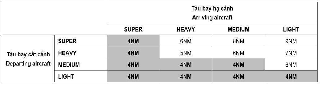
-
The ATS/SMR are in normal operation, the objects are accurately displayed as standard requirement;
-
The screen of ATM system is displayed to monitor full final approach segment (within 10 NM from the threshold of RWY). The SMR is in normal operation and is able to monitor the last 4 km (2 NM) of the final approach segment;
-
ATC monitors aircraft trajectory and recommends promptly when realizing the risk of landing on the wrong RWY.
-
-
In case of without ATS surveillance: ATC must ensure that the take-off clearances are issued 3 minutes before the aircraft’s estimated land ing time on the final approach track of RWY 29L (4 minutes in case of light aircraft flying after heavy aircraft).
-
When using the intersection of RWY 29R and TWY P8 for take-off:
-
Aircraft is not allowed to hold short of TWY P8 (between two RWYs) when the other landing aircraft is approaching on RWY 29L;
-
Aircraft at the intersection of RWY 29R and TWY P8 starts running for take-off when at the same time another landing aircraft is approaching at 3 NM or more on the final approach track of RWY 29L.
-
5.2.5 Operational option 5: Both RWYs 11L and 11R are used for take-off.
-
ATCs do not allow aircraft to line-up two RWYs at the same time for take-off in order to avoid mistaking take-off clearance from ATC;
-
This operation option is limited to use.
5.2.6 Operational option 6: Both RWYs 11L and 11R are used for landing.
-
Used as one RWY;
-
This operation option is limited to use due to no capability of standby.
5.2.7 Operational option 7: Both RWYs 29L and 29R are used for take-off.
-
ATCs do not allow aircraft to line-up two RWYs at the same time to take off in order to avoid mistaking take-off clearance from ATC;
-
This operation option is limited to use.
5.2.8 Operational option 8: Both RWYs 29L and 29R are used for landing.
-
Used as one RWY;
-
This operation option is limited to use due to no capability of standby.
5.3 ATC responsibilities
-
General requirement:
-
Must be fully trained about the operational options of the two parallel runways of this procedure;
-
Enhance aircraft observation and monitoring, issue clear and timely clearance, request and listen to the pilot read back the clearance to ensure that the clearance is fully received and comprehended.
-
-
For departure aircraft:
-
Departure aircraft are not allowed to line up two parallel runways simultaneously for departure;
-
Base on the specific ATC situation, clearances are able to be issued simultaneously for aircraft to line up RWY and take off to increase throughout capacity.
-
-
For landing aircraft:
-
Have action and measure to ensure that approaching aircraft land on the correct assigned RWY;
-
Concentrate on monitoring aircraft, enhance observation aircraft on final leg and remind pilot if necessary.
-
5.4 Pilots responsibilities
-
General requirement: Pilots shall fully understand and implement standard operational procedures (SOP) and these operational procedures; focus on observing, strictly complying and implementing ATC clearances fully in a timely manner to reduce RWY occupation time.
-
For departure aircraft:
-
Pilots shall be ready for take-off; ensure that aircraft shall be held on the assigned holding point as requested by ATC.
-
Expedite to carry out the line up RWY and the take-off clearances provided.
-
Pilots shall ensure that aircraft start rolling for take-off within 30 seconds after receiving take-off clearance (if the aircraft is unable to do so, pilots shall inform Noi Bai TWR immediately).
-
-
For landing aircraft:
-
For aircraft within approaching stage, ensure the compliance the IAS is as followed:
-
From 350 km/h - 370 km/h (190 kt - 200 kt) when aircraft is at base leg or nearly into final approach or when at the distance of 25 NM from THR of RWY;
-
From 300 km/h - 335 km/h (160 kt - 180 kt) when aircraft is at the distance of 10 NM from THR of RWY;
-
From 280 km/h - 300 km/h (150 kt - 160 kt) when aircraft is at the distance of 5 NM from THR of RWY.
-
-
In case the aircraft can not in compliance with the IAS above, pilot shall immediately inform the ATC;
-
After landing, pilots must vacate RWYs within 60 seconds from the time the aircraft crosses THR until it completely passes holding position of exit TWY (if the aircraft is unable to do so, pilots shall inform Noi Bai TWR immediately).
-
6 Arrival, departure manager system (AMAN/DMAN)
6.1 Purpose
The AMAN/DMAN is implemented to manage, sequence arrival and departure flights at Noi Bai international Airport, improve the capacity of airspace and aerodromes operations within Ha Noi FIR in particular and in Viet Nam in general.
6.2 Scope
Automated ATM system, related equipment systems, the air navigation services (ANS) units: Ha Noi ACC and Noi Bai APP/TWR and the other ANS units relating to ANS provisions of the Northern Region Air Traffic Services Company.
6.3 Subject of application
Viet Nam Air Traffic Management Corporation: Northern Region Air Traffic Services, Viet Nam Aeronautical Information Centre and the others related departments/units.
The others departments/units related to the implementation of AMAN/DMAN at Noi Bai International Airport: Noi Bai International Airport; the Airlines to/from Noi Bai International Airport; the Ground Services Companies at Noi Bai International Airport.
6.4 AMAN system
Base on flight plan data, surveillance data and related meteorological data, AMAN calculates, arranges and provides the shortest flight trajectory for each flight. During flight landing process calculation, AMAN establishes 3 processing areas, in which flights are calculated, sequenced and can be changed the order to match the actual air traffic situation. Flights are closer to the destination airport will expect less change in arriving sequence. These 3 processing areas of AMAN include:
The “free part” is the area where AMAN will sequence arrival flights based on flight plans. STA and arrival sequence are constantly updated based on surveillance data and actual flight trajectory, therefore, arriving sequence can be automatically changed due to calculations of the system.
The “frozen part” is the area where AMAN will not automatically insert new flights or change the order of flights to sustain landing sequence . Under unusual circumstances, ATC may change landing sequence to handle situations.
The “final part” is the area after the aircraft have passed the final approach fix (FAF). AMAN updates the aircraft's STA for the last time at the FAF. In this area, AMAN will not change the sequence and flight’s STA.
10 minutes before the aircraft enters Ha Noi FIR, the AMAN/DMAN system will start calculating, sequencing and displaying the flight's STA on AMAN/DMAN screen. STA is continuously updated by the system according to the actual trajectory of the flight.
a) Holding advice:
When AMAN calculates and achieves the optimal sequence of arrivals, it may recommend that some flights have to wait at the designated holding areas.
In case the speed control is not achieved and the flight must be brought into the holding pattern, AMAN will monitor the flight and reduce the remained holding time of flight when a new trajectory is calculated.
b) Speed advice:
To achieve the desired sequence, during the calculation, AMAN can make recommendations to increase/reduce speed of a certain flight. Recommendations are given in Mach number (if the aircraft is in an en-route phase) or CAS (if the aircraft is in a descent phase) and AMAN assumes that there is no difference between Indicated Airspeed (IAS) and Calibrated Airspeed (CAS).
6.5 DMAN system
Operational principles
-
Based on flight plan data (EOBT) and wake turbulence separation standards, aircraft parking positions, taxiway configuration, runway, runway operating limitations, priority level of the flight ... DMAN calculates to provide departure sequence of aircrafts with two estimated times for the flight: Target take-off time (TTOT) and Target startup approves time (TSAT).
-
Besides, based on the principle of grouping arrival aerodromes by distance, aircraft turbulence category and actual air traffic situation, ATC can adjust/change the sequence of departing aircrafts, ensure the safety, order and efficiency of flight operations at Noi Bai International Airport.
-
60 minutes before the EOBT of the flight, the AMAN/DMAN system will calculate and display the TSAT and TTOT, sequences of the flights on the AMAN/DMAN system and will be shared with related departments/units through the AMAN/DMAN sharing screen.
-
Changing EOBT of a flight will result in the system recalculating the TSAT and changing the flight’s departure sequence.
6.6 Flight planning of airlines
Arrivals shall be calculated by AMAN and be arranged sequence on the Timeline when meeting the following requirements:
Field 15 of the flight plan shall be fully filled, especially the shortest arrival procedure;
Arrival procedure of flight shall be complied with RWY using mode established at AMAN/DMAN terminal at operating time (assigned by Watch-supervisor of Noi Bai TWR).
Departures shall be calculated by DMAN and be arranged sequence on the Timeline when meeting the following requirements:
Field 15 of the flight plan shall be fully filled, especially departure procedure;
SID of flight shall be complied with RWY using mode established at AMAN/DMAN terminal at operating time (assigned by Watch-supervisor of Noi Bai TWR).
6.7 Coordination procedure processing data arrival and departure manager system (AMAN/DMAN)
This procedure is applied to flights arriving to and departing from Noi Bai International Airport when apply AMAN/DMAN (except for VIP flights, special flights, flights with technical problems and emergency flight which are prioritised in accordance with current regulations).
Data of the designated times for Scheduled Time of Arrival (STA), Actual Time of Arrival (ATA) of the flight will be calculated by the AMAN/DMAN system and displayed on the system 10 minutes before the arriving flight enters Ha Noi FIR.
Based on the STA, related units must ensure that the aircraft stand/passenger boarding bridge, facilities and vehicles are ready to serve the flight at least 5 minutes before the time the aircraft taxi into stand/passenger boarding bridge.
ATC ensures to coordinate and unify with pilot to effectively comply with AMAN's recommendations for flights such as increase/reduce speed, using the holding pattern, extend or shorten the track, etc., depending on the air traffic situation.
a) Responsibility of pilot
Co-operating and complying with the ATCs' clearances to follow AMAN's recommendations for flights such as increase/reduce speed, using the holding pattern, extend or shorten the track... depending on the air traffic situation. Early notifying ATC if pilot is unable to comply with an alternative plan.
Comply with the regulations on speed control in the air and on the movement area:
Air speed control:
All aircrafts using SID/STAR RNAV 1 shall follow the speed restrictions specified in the flight procedures (published in AIP Viet Nam). If unable to follow the speed restrictions, pilot shall inform ATC immediately and report expected speed.
Speed restriction within Noi Bai TMA are as follows:
* Aircraft under FL 100: Maximum speed 250 kt (IAS).
* Arrival aircraft is 12 NM (track mile) from touchdown: Maximum speed 200 kt (IAS).
* Arrival aircraft is 5 NM (track mile) from touchdown: Maximum speed 160 kt (IAS).
Speed control on movement area:
Aircraft taxiing speed into stand equipped with visual docking guidance system (VDGS): As published in AIPViet Nam, Item VVNB AD 2.9.
Aircraft taxiing speed at the movement area:
* RWY area: Not exceed 40 kts;
* TWY area: Not exceed 30 kts when the aircraft is performing a straight taxi;
* Apron area: Not exceed 15 kts before approaching the last turn to the parking; not exceed 10 kts when turning in the last turn to the parking (with marshaller), then reduce speed to approach the stand, stop right at the stop line.Pilots must strictly follow the marshaller’ instructions, including the signal requesting to reduce speed (if any).
When taxiing aircraft makes a turn of 90° or more: Not exceed 10 kts.
In low visibility operation (LVO): Not exceed 10 kts.
In order to reduce RWY occupancy time and expedite the air traffic flow, pilots must immediately perform the RWY vacating clearance and ensure that the tail of the aircraft vacate the relevant holding position within the time not exceeding 60 seconds after rolling out; immediately notify Noi Bai TWR if unable to perform.
b) Flight plan procedure of airlines
Field 15 of the flight plan shall be fully filled, especially the shortest arrival procedure (STAR) complied with RWY operating mode at Noi Bai International Airport.
Arrival procedures when using RWY 11L/R include: BISON 1L/1R, HAKAO 1N/1R, HUVAN 1N/1R, MUCHI 1L/1R, TAMDA 1N/1R.
Arrival procedures when using RWY 29L/R include: BISON 1P/1Q, HAKAO 1P/1Q, HUVAN 1P/1Q, MUCHI 1P/1Q, TAMDA 1P/1Q.
60 minutes before the Estimated Off-Block Time (EOBT) of flight, DMAN will calculate and display the Target Start-up Approval Time (TSAT) and Target Take-of Time (TTOT) in the system. After exploiting on the AMAN/DMAN sharing screen, airlines (domestic and international), Viet Nam Airport Ground Services (VIAGS), Ha Noi Ground Services (HGS) are responsible to inform the TSAT, TTOT of the flight to the pilot.
After the TSAT of flight is displayed on the AMAN/DMANsharing screen, the airline's representative (domestic/international), ground services unit are responsible to inform ATC operating AMAN/DMAN the updated/revised TOBT/EOBT of the flight in case there is a deviation of 5 minutes or more. The change of TOBT/EOBT shall be limited (not more than 3 times) to ensure the stability of the TTOT calculation process.
ATC will notify the pilot if there is a change the TSAT of the flight (after the time the pilot has contacted ATC for ATC clearance).
a) Responsibilities of the pilot:
At least 15 minutes before the EOBT, pilots shall ensure to contact ATC - Clearance delivery position (119.25 MHz) for ATC clearance.
Receive information about TSAT, TTOT of flight from airline’s representative (domestic/international); initiatively co-operate to implement the flight preparation procedures to ensure the compliance with the TSAT and TTOT of flight.
± 5 minutes of TSAT, the pilot contacts GCU Noi Bai (121.9 MHz) to request for startup/pushback (after receiving the ATC clearance). If more than 5 minutes after receiving the clearance, the aircraft does not startup/pushback due to not being ready, the TSAT of flight will be cancelled (except in case of aircraft condition on the apron), ATC will not issue clearance approving for tow/push to start engine and require the pilot to notify the airline, flight company/ground service/ground services unit updated new TOBT/EOBT to receive the TSAT of flight.
In order to reduce RWY occupancy time and expedite the air traffic flow, the pilots must be prompt to line up RWY, rolling for take-off within 30 seconds since receiving take-off clearance. Immediately notify Noi Bai TWR if unable to perform.
Comply with regulations on speed control on the movement area as mentioned in Item a. part 6.7.1.
b) Flight plan procedure of airlines
Field 15 of the flight plan shall be fully filled, especially departure procedure (SID) complied with RWY operating mode at Noi Bai International Airport.
Departure procedures when using RWY 11L/R include: JULUN 1A/1B, BUNBO 1A/1B, TINLY 1A/1B, MUCHI 1A/1B, HUVAN 1D/1E.
Departure procedures when using RWY 29L/R include: JULUN 1C/1D, DIHAI 1A/1B, FINAM 1A/1B, XUNBI 1A/1B, LENNU 1A/1B.
Note: In case of changing the submitted flight plan:
If a flight with submitted filled flight plan may be delayed 30 minutes or more than the EOBT filled in the flight plan. The pilot/ airline’s representative /ARO shall immediately notify TWR Noi Bai or the Air Traffic Services Reporting Office (ARO) at Noi Bai International Airport to issue a DELAY message as regulated.
If the flight is delayed more than 60 minutes of the EOBT filled in the flight plan, the pilots/airline’s representative/ARO shall revise the flight plan or submit a new flight plan.
For flights departing from the application of Level 3 multi-nodal ATFM airports and airspace submitted filled flight plan and others information relating to ATS transmit message (including message DLA, CNL, CHG) shall adhere to the following Level 2 multi-nodal ATFM operation procedures in Viet Nam.
c) Chart the coordination procedures process the implementation of AMAN/DMAN system
7 Place safety cones around the aircraft
In case of need to mark stop line, safety cones will be placed on the both sides of the stop line, 2 M to 3 M from the centre line of the taxilane to stand before aircraft taxi into stand.
8 List of non-compliance
| Number | Non Compliance | Mitigation Measure |
|---|---|---|
| 1 | SWY LGTs have not been installed | See link detail: https://english.caa.gov.vn/doc/airport-management/others.html |
| 2 | Some equipment installed in the RWY strip is do not meet the facility requirements. | |
| 3 | The navigation station is located within < 120 M from the runway centreline does not meet the facility requirements |
VVNB AD 2.24 CHARTS RELATED TO NOI BAI AERODROME
|
Chart name |
Page |
|---|---|
|
Aerodrome Chart – ICAO | AD 2-VVNB-2-1 |
|
AD Operating Minima | AD 2-VVNB-3-1 |
|
AD Operating Minima (cont.) | AD 2-VVNB-3-2 |
|
Aircraft Parking/Docking Chart – ICAO | AD 2-VVNB-4-1 |
|
The INS coordinates and elevation for ACFT Stands | AD 2-VVNB-4-2 |
|
The INS coordinates and elevation for ACFT Stands (cont.) | AD 2-VVNB-4-3 |
|
Aerodrome Ground Movement Chart – ICAO | AD 2-VVNB-5-1 |
|
Aerodrome Obstacle Chart – ICAO – Type A (Operating limitations) – RWY 11R/29L | AD 2-VVNB-6-1 |
|
Aerodrome Obstacle Chart – ICAO – Type A (Operating limitations) – RWY 11L/29R | AD 2-VVNB-6-3 |
|
Aerodrome Obstacle Chart – ICAO – Type B | AD 2-VVNB-6-5 |
|
Precision Approach Terrain Chart - ICAO | AD 2-VVNB-7-1 |
|
Area Chart – ICAO | AD 2-VVNB-8-1 |
|
Standard Departure Chart – Instrument (SID) – ICAO – RWY 11L/R: HAKAO 2A, VITRA 2A, VINHA 2A, TONGA 2A, HUVAN 2A, PHUTA 2A | AD 2-VVNB-9-1 |
|
Standard Departure Chart – Instrument (SID) – ICAO – RWY 11L/R: HAKAO 2C, VINHA 2C, TRANA 2A, HUVAN 2C | AD 2-VVNB-9-3 |
|
Standard Departure Chart – Instrument (SID) – ICAO – RWY 29L/R: HAKAO 2B, VITRA 2B, VINHA 2B, TONGA 2B, HUVAN 2B, PHUTA 2B | AD 2-VVNB-9-5 |
|
Standard Departure chart – Instrument (SID) – ICAO – RWY 11L/R; 29L/R: TAMDA 3A, TAMDA 3B | AD 2-VVNB-9-7 |
|
Standard Departure Chart – Instrument (SID) – ICAO – RNAV RWY 11L/R: JULUN 1A/1B, BUNBO 1A/1B, TINLY 1A/1B, MUCHI 1A/1B, HUVAN 1D/1E | AD 2-VVNB-9-9 |
|
Standard Departure Chart – Instrument (SID) – ICAO – RNAV RWY 11L/R: JULUN 1A/1B, BUNBO 1A/1B, TINLY 1A/1B, MUCHI 1A/1B, HUVAN 1D/1E (Procedure coding) | AD 2-VVNB-9-10 |
|
Standard Departure Chart – Instrument (SID) – ICAO – RNAV RWY 11L/R: JULUN 1A/1B, BUNBO 1A/1B, TINLY 1A/1B, MUCHI 1A/1B, HUVAN 1D/1E (Procedure coding (cont.)) | AD 2-VVNB-9-11 |
|
Standard Departure Chart – Instrument (SID) – ICAO – RNAV RWY 29L/R: JULUN 1C/1D, DIHAI 1A/1B, FINAM 1A/1B, XUNBI 1A/1B, LENNU 1A/1B | AD 2-VVNB-9-13 |
|
Standard Departure Chart – Instrument (SID) – ICAO – RNAV RWY 29L/R: JULUN 1C/1D, DIHAI 1A/1B, FINAM 1A/1B, XUNBI 1A/1B, LENNU 1A/1B (Procedure coding) | AD 2-VVNB-9-14 |
|
Standard Departure Chart – Instrument (SID) – ICAO – RNAV RWY 29L/R: JULUN 1C/1D, DIHAI 1A/1B, FINAM 1A/1B, XUNBI 1A/1B, LENNU 1A/1B (Procedure coding (cont.)) | AD 2-VVNB-9-15 |
|
Standard Departure Chart – Instrument (SID) – ICAO – RNAV RWY 29L/R: JULUN 1C/1D, DIHAI 1A/1B, FINAM 1A/1B, XUNBI 1A/1B, LENNU 1A/1B (Procedure coding (cont.)) | AD 2-VVNB-9-16 |
|
Standard Arrival Chart – Instrument (STAR) – ICAO – RWY CHC 11L/R: HAKAO 2A, NAH 1A, MC 1A, LAOCA 2A, BQ 3A, PHUTA 2A, XIVIN 1A | AD 2-VVNB-11-1 |
|
Standard Arrival Chart – Instrument (STAR) – ICAO – RWY 11L/R: TAMDA 3A | AD 2-VVNB-11-3 |
|
Standard Arrival Chart – Instrument (STAR) – ICAO – RWY 29L/R: HAKAO 2B, NAH 1B, MC 2B, LAOCA 2B, BQ 3B, PHUTA 2B, XIVIN 1B | AD 2-VVNB-11-5 |
|
Standard Arrival Chart – Instrument (STAR) – ICAO (Overlay to radar vector pattern) – RNAV RWY 11L: TAMDA 1J, HAKAO 1K, BISON 1F, MUCHI 1H, HUVAN 1L | AD 2-VVNB-11-7 |
|
Standard Arrival Chart – Instrument (STAR) – ICAO (Overlay to radar vector pattern) – RNAV RWY 11L: TAMDA 1J, HAKAO 1K, BISON 1F, MUCHI 1H, HUVAN 1L (Procedure coding) | AD 2-VVNB-11-8 |
|
Standard Arrival Chart – Instrument (STAR) – ICAO (Overlay to radar vector pattern) – RNAV RWY 11L: TAMDA 1J, HAKAO 1K, BISON 1F, MUCHI 1H, HUVAN 1L (Procedure coding (cont.)) | AD 2-VVNB-11-9 |
|
Standard Arrival Chart – Instrument (STAR) – ICAO (Overlay to radar vector pattern) – RNAV RWY 11L: TAMDA 1K, HAKAO 1L, BISON 1G, MUCHI 1J, HUVAN 1M | AD 2-VVNB-11-11 |
|
Standard Arrival Chart – Instrument (STAR) – ICAO (Overlay to radar vector pattern) – RNAV RWY 11L: TAMDA 1K, HAKAO 1L, BISON 1G, MUCHI 1J, HUVAN 1M (Procedure coding) | AD 2-VVNB-11-12 |
|
Standard Arrival Chart – Instrument (STAR) – ICAO (Overlay to radar vector pattern) – RNAV RWY 11L: TAMDA 1K, HAKAO 1L, BISON 1G, MUCHI 1J, HUVAN 1M (Procedure coding (cont.)) | AD 2-VVNB-11-13 |
|
Standard Arrival Chart – Instrument (STAR) – ICAO (Overlay to radar vector pattern) – RNAV RWY 11L: TAMDA 1L, HAKAO 1M | AD 2-VVNB-11-15 |
|
Standard Arrival Chart – Instrument (STAR) – ICAO (Overlay to radar vector pattern) – RNAV RWY 11L: TAMDA 1L, HAKAO 1M (Procedure coding) | AD 2-VVNB-11-16 |
|
Standard Arrival Chart – Instrument (STAR) – ICAO (Overlay to radar vector pattern) – RNAV RWY 11L: TAMDA 1N, HAKAO 1N, BISON 1L, MUCHI 1L, HUVAN 1N | AD 2-VVNB-11-17 |
|
Standard Arrival Chart – Instrument (STAR) – ICAO (Overlay to radar vector pattern) – RNAV RWY 11L: TAMDA 1N, HAKAO 1N, BISON 1L, MUCHI 1L, HUVAN 1N (Procedure coding) | AD 2-VVNB-11-18 |
|
Standard Arrival Chart – Instrument (STAR) – ICAO (Overlay to radar vector pattern) – RNAV RWY 11R: TAMDA 1C, HAKAO 1D, BISON 1A, MUCHI 1C, HUVAN 1F | AD 2-VVNB-11-19 |
|
Standard Arrival Chart – Instrument (STAR) – ICAO (Overlay to radar vector pattern) – RNAV RWY 11R: TAMDA 1C, HAKAO 1D, BISON 1A, MUCHI 1C, HUVAN 1F (Procedure coding) | AD 2-VVNB-11-20 |
|
Standard Arrival Chart – Instrument (STAR) – ICAO (Overlay to radar vector pattern) – RNAV RWY 11R: TAMDA 1C, HAKAO 1D, BISON 1A, MUCHI 1C, HUVAN 1F (Procedure coding (cont.)) | AD 2-VVNB-11-21 |
|
Standard Arrival Chart – Instrument (STAR) – ICAO (Overlay to radar vector pattern) – RNAV RWY 11R: TAMDA 1F, HAKAO 1G, BISON 1D, MUCHI 1D, HUVAN 1G | AD 2-VVNB-11-23 |
|
Standard Arrival Chart – Instrument (STAR) – ICAO (Overlay to radar vector pattern) – RNAV RWY 11R: TAMDA 1F, HAKAO 1G, BISON 1D, MUCHI 1D, HUVAN 1G (Procedure coding) | AD 2-VVNB-11-24 |
|
Standard Arrival Chart – Instrument (STAR) – ICAO (Overlay to radar vector pattern) – RNAV RWY 11R: TAMDA 1F, HAKAO 1G, BISON 1D, MUCHI 1D, HUVAN 1G (Procedure coding (cont.)) | AD 2-VVNB-11-25 |
|
Standard Arrival Chart – Instrument (STAR) – ICAO (Overlay to radar vector pattern) – RNAV RWY 11R: TAMDA 1H, HAKAO 1J | AD 2-VVNB-11-27 |
|
Standard Arrival Chart – Instrument (STAR) – ICAO (Overlay to radar vector pattern) – RNAV RWY 11R: TAMDA 1H, HAKAO 1J (Procedure coding) | AD 2-VVNB-11-28 |
|
Standard Arrival Chart – Instrument (STAR) – ICAO (Overlay to radar vector pattern) – RNAV RWY 11R: TAMDA 1R, HAKAO 1R, BISON 1R, MUCHI 1R, HUVAN 1R | AD 2-VVNB-11-29 |
|
Standard Arrival Chart – Instrument (STAR) – ICAO (Overlay to radar vector pattern) – RNAV RWY 11R: TAMDA 1R, HAKAO 1R, BISON 1R, MUCHI 1R, HUVAN 1R (Procedure coding) | AD 2-VVNB-11-30 |
|
Standard Arrival Chart – Instrument (STAR) – ICAO (Overlay to radar vector pattern) – RNAV RWY 29L/R: TAMDA 1G/1M, HAKAO 1H/1S, BISON 1E/1S, MUCHI 1G/1K, HUVAN 1K/1S | AD 2-VVNB-11-31 |
|
Standard Arrival Chart – Instrument (STAR) – ICAO (Overlay to radar vector pattern) – RNAV RWY 29L/R: TAMDA 1G/1M, HAKAO 1H/1S, BISON 1E/1S, MUCHI 1G/1K, HUVAN 1K/1S (Procedure coding) | AD 2-VVNB-11-32 |
|
Standard Arrival Chart – Instrument (STAR) – ICAO (Overlay to radar vector pattern) – RNAV RWY 29L/R: TAMDA 1G/1M, HAKAO 1H/1S, BISON 1E/1S, MUCHI 1G/1K, HUVAN 1K/1S (Procedure coding (cont.)) | AD 2-VVNB-11-33 |
|
Standard Arrival Chart – Instrument (STAR) – ICAO (Overlay to radar vector pattern) – RNAV RWY 29L/R: TAMDA 1G/1M, HAKAO 1H/1S, BISON 1E/1S, MUCHI 1G/1K, HUVAN 1K/1S (Procedure coding (cont.)) | AD 2-VVNB-11-34 |
|
Standard Arrival Chart – Instrument (STAR) – ICAO (Overlay to radar vector pattern) – RNAV RWY 29L/R: TAMDA 1D/2E, HAKAO 1E/2F, BISON 1B/2C, MUCHI 1E/2F, HUVAN 1H/2J | AD 2-VVNB-11-35 |
|
Standard Arrival Chart – Instrument (STAR) – ICAO (Overlay to radar vector pattern) – RNAV RWY 29L/R: TAMDA 1D/2E, HAKAO 1E/2F, BISON 1B/2C, MUCHI 1E/2F, HUVAN 1H/2J (Procedure coding) | AD 2-VVNB-11-36 |
|
Standard Arrival Chart – Instrument (STAR) – ICAO (Overlay to radar vector pattern) – RNAV RWY 29L/R: TAMDA 1D/2E, HAKAO 1E/2F, BISON 1B/2C, MUCHI 1E/2F, HUVAN 1H/2J (Procedure coding (cont.)) | AD 2-VVNB-11-37 |
|
Standard Arrival Chart – Instrument (STAR) – ICAO (Overlay to radar vector pattern) – RNAV RWY 29L/R: TAMDA 1D/2E, HAKAO 1E/2F, BISON 1B/2C, MUCHI 1E/2F, HUVAN 1H/2J (Procedure coding (cont.)) | AD 2-VVNB-11-38 |
|
Standard Arrival Chart – Instrument (STAR) – ICAO (Overlay to radar vector pattern) – RNAV RWY 29L/R: TAMDA 1D/2E, HAKAO 1E/2F, BISON 1B/2C, MUCHI 1E/2F, HUVAN 1H/2J (Procedure coding (cont.)) | AD 2-VVNB-11-39 |
|
Standard Arrival Chart – Instrument (STAR) – ICAO (Overlay to radar vector pattern) – RNAV RWY 29L/R: TAMDA 1P/1Q, HAKAO 1P/1Q, BISON 1P/1Q, MUCHI 1P/1Q, HUVAN 1P/1Q | AD 2-VVNB-11-41 |
|
Standard Arrival Chart – Instrument (STAR) – ICAO (Overlay to radar vector pattern) – RNAV RWY 29L/R: TAMDA 1P/1Q, HAKAO 1P/1Q, BISON 1P/1Q, MUCHI 1P/1Q, HUVAN 1P/1Q (Procedure coding) | AD 2-VVNB-11-42 |
|
Standard Arrival Chart – Instrument (STAR) – ICAO (Overlay to radar vector pattern) – RNAV RWY 29L/R: TAMDA 1P/1Q, HAKAO 1P/1Q, BISON 1P/1Q, MUCHI 1P/1Q, HUVAN 1P/1Q (Procedure coding (cont.)) | AD 2-VVNB-11-43 |
|
Standard Arrival Chart – Instrument (STAR) – ICAO (Overlay to radar vector pattern) – RNAV RWY 29L/R: TAMDA 1P/1Q, HAKAO 1P/1Q, BISON 1P/1Q, MUCHI 1P/1Q, HUVAN 1P/1Q (Procedure coding (cont.)) | AD 2-VVNB-11-44 |
|
Standard Arrival Charts – Instrument (STAR) – ICAO – RNAV RWY 11L/R: BIVIM 1A TRANSITION | AD 2-VVNB-11-45 |
|
Standard Arrival Charts – Instrument (STAR) – ICAO – RNAV RWY 11L/R: BIVIM 1A TRANSITION (Bảng miêu tả, phương thức chờ và danh mục lộ điểm) | AD 2-VVNB-11-46 |
|
Standard Arrival Charts – Instrument (STAR) – ICAO – RNAV RWY 29L/R: BIVIM 1B TRANSITION | AD 2-VVNB-11-47 |
|
Standard Arrival Charts – Instrument (STAR) – ICAO – RNAV RWY 29L/R: BIVIM 1B TRANSITION (Tabular description, holding procedure and waypoint list) | AD 2-VVNB-11-48 |
|
ATC Surveillance Minimum Altitude Chart – ICAO | AD 2-VVNB-12-1 |
|
Instrument Approach Chart – ICAO: VOR Y RWY 11L | AD 2-VVNB-13-1 |
|
Instrument Approach Chart – ICAO: VOR Z RWY 11L | AD 2-VVNB-13-3 |
|
Instrument Approach Chart – ICAO: VOR Y RWY 11R | AD 2-VVNB-13-5 |
|
Instrument Approach Chart – ICAO: VOR Z RWY 11R | AD 2-VVNB-13-7 |
|
Instrument Approach Chart – ICAO: VOR RWY 29L | AD 2-VVNB-13-9 |
|
Instrument Approach Chart – ICAO: VOR Y RWY 29R | AD 2-VVNB-13-11 |
|
Instrument Approach Chart – ICAO: ILS Y RWY 11L CAT I | AD 2-VVNB-13-13 |
|
Instrument Approach Chart – ICAO: ILS Z RWY 11L CAT I | AD 2-VVNB-13-15 |
|
Instrument Approach Chart – ICAO: ILS Y RWY 11R CAT I & CAT II | AD 2-VVNB-13-17 |
|
Instrument Approach Chart – ICAO: ILS Z RWY 11R CAT I & CAT II | AD 2-VVNB-13-19 |
|
Instrument Approach Chart – ICAO: ILS X RWY 29L | AD 2-VVNB-13-21 |
|
Instrument Approach Chart – ICAO: ILS Y RWY 29L | AD 2-VVNB-13-23 |
|
Instrument Approach Chart – ICAO: ILS Z RWY 29L | AD 2-VVNB-13-25 |
|
Instrument Approach Chart – ICAO: ILS Y RWY 29R | AD 2-VVNB-13-27 |
|
Instrument Approach Chart – ICAO: ILS Z RWY 29R | AD 2-VVNB-13-29 |
|
Visual Approach Chart – ICAO | AD 2-VVNB-14-1 |